That suggests inadequate decoupling in the B+ lines. Three stage amplifiers fundamentally have positive feedback from output stage B+ to first stage B+. You might experiment with adding some capacitance to see if it moves the curves.
All good fortune,
Chris
All good fortune,
Chris
Ohhh how dumb I am! That could be the reason for 15.9Hz wiggle, I'll test it with 470u cap and report it.How about the second LC tank, where L=1H and C=100u? Try increasing C to 400u and measure again. You could also increase choke Rdc.
Thanks for all the help.
Hi again, I replaced the second LC filter 100u cap with 440u and here is the results compared to 100u original cap:Try increasing C to 400u and measure again. You could also increase choke Rdc.
It seems you were right about the LC resonance and I completely forgot about the second LC filter causing the issue.
Now Lo is at around 7.5 Hz and Xc at this frequency is around 48.5R and I need around 1.41 x 48 = 68R series resistance to be able to damp this resonance. The choke's DC resistance is 23R, so next step is to add a 47R series resistance to see if it helps.
Thanks
Sajad
Next update: I added 47R to 100R resistors in series with 1H inductor and both didn't help at all, the gragh is exactly the same as before.
Next update: increased the PA cathode cap from 68u to 100u and now the bump is just 0.05 dB compared to 0.25 dB before:If cathode capacitor is 68u, try increasing it as well.
Hi again, today I increased the first filter cap (the one after 47u reservoir cap) from 100u to 220u, and settled on 440u for the second filter cap and 100u cathode caps; here is the final results:

Now I'm pretty happy with the results, and now it's time to improve the slew rate I not sure maybe by biasing the driver stage hotter or using another driver...
Thanks to everybody for helping me through these wild resonances.😀
Best regards.
Sajad
Now I'm pretty happy with the results, and now it's time to improve the slew rate I not sure maybe by biasing the driver stage hotter or using another driver...
Thanks to everybody for helping me through these wild resonances.😀
Best regards.
Sajad
Hi again, today I increased the first filter cap (the one after 47u reservoir cap) from 100u to 220u, and settled on 440u for the second filter cap and 100u cathode caps; here is the final results:
View attachment 1389863
Now I'm pretty happy with the results, and now it's time to improve the slew rate I not sure maybe by biasing the driver stage hotter or using another driver...
Thanks to everybody for helping me through these wild resonances.😀
Best regards.
Sajad
Interesting! Good thing you didn't listen to me! ;-)
Thanks for sharing your design, it seems promising. Can I use 12BH7 for the first preamp stage as well? What values of anode and cathode resistors and caps do you suggest?For example I usually use 12BH7a instead of 12AU7 in the driver position.
Higher voltage, higher current, lower output impedance (higher driving capacity), lower THD.
Sample:
View attachment 1389938
IMO 12BH7a "too good" tube to use as simple VAS stage.
In my simulation the 12BH7 gain about 15dB, the first gain stage has about 22dB, overall about 72x.
Any gain chain (VAS+driver) which have enough gain (power tube grid swing/estimated input swing), and enough driving capacity/enough low output impedance is appropriate.
BTW many "interesting" 12AU7 variant/substitute exist.
For example I have RCA cleartop, RCA 5963, many 6211 variant.
Thank you so much, Can you give a link to tube models for LTspice which you use? For example the 6336.Any gain chain (VAS+driver) which have enough gain (power tube grid swing/estimated input swing), and enough driving capacity/enough low output impedance is appropriate.
Download and use Stephie (Steve) Bench tube models.
https://forum.intactaudio.com/viewforum.php?f=15&sid=81218fc46a309706dfeab426fcd2f2c3
https://forum.intactaudio.com/viewtopic.php?f=15&t=523
https://forum.intactaudio.com/viewforum.php?f=15&sid=81218fc46a309706dfeab426fcd2f2c3
https://forum.intactaudio.com/viewtopic.php?f=15&t=523
Attachments
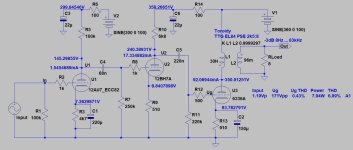
Hi everyone, after weeks of tweaking this amp finally I was able to get the best out of this tube, now it's one of the best SET's I've ever heard.
Here is the final schematics and test results:


Here is the final schematics and test results:
Are you measuring the frequency response using a fast sweep (chirp) test? That method of testing will often produce wiggles at LF in circuits using transformers or inductors. Spot measurement will confirm.
Hi Merlin, I always use the longest sweep with REW software and it seems this problem was due to undamped resonances from PSU LC filters and it was resolved by increasing filter caps and series resistance as shown on the final version tests.Are you measuring the frequency response using a fast sweep (chirp) test? That method of testing will often produce wiggles at LF in circuits using transformers or inductors. Spot measurement will confirm.
Glad to meet you here, I started tube diy with your website and PSU design book.
- Home
- Amplifiers
- Tubes / Valves
- SET amp wiggling in the low frequency response
