Howdy. Newbie learning how to scale the current capabilities of a regulator with transistors.
There are plenty of examples on the web and elsewhere of circuits of series pass regulators with transistors "driven" by a zenor diode setting the reference voltage for the transistor base.
Page 29 and 30 of this On-Semi document show configurations for a 3-terminal IC regulator with a sense lead driving the base of an NPN transistor and a schematic for a 3-terminal IC regulator without a sense lead driving a PNP transistor. Elliot Sound shows what seems to be a very different schematic (fig 7 here) where Vout of the IC regulator doesn't seem to be driving the base of the transistor.
I am therefore a little confused as it has been suggested to me that I should consider a set up where a precision 3 terminal regulator (without a sense lead) would drive a NPN transistor (like a 2SC3264). I think I understand the concept of zener diode or 3 terminal regulator "anchoring" the voltage of a pass transistor while shifting the burden of current from the precision regulator to the transistor. I'm just a bit unsure how one would wire the two.
Also, one is obviously forced to consider such a setup if the current demands of the load exceed the limits of the precision regulator, but are there advantages to such a setup even if the current need is within (albeit towards the top of) the capability of the precision regulator? (i.e. does the burden sharing result in some sort of efficiency, precision or other gains?)
http://sound.westhost.com/articles/vi-regulators.html
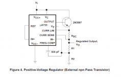
fig4-1b on p30 shows the PNP with sensing resistor feeding voltage to the external transistor BE junction.
At very low current demand when the Vbe across the sense resistor is below ~300mVbe the external transistor is OFF, i.e. passes nothing to the load.
The 3pin reg supplies the whole demand.
At higher demand the Vbe increases and @ ~400mVbe turns on the external transistor.
Both the reg and the transistor now supply current to the load.
When the output voltage gets too high the reg turns down it's output and this reduces the current through the sensing resistor. i.e. also turns down the external transistor.
The effect of this is that the specifications for load and input regulation of the reg control the stability of the output.
When the NPN is used, Fig 4-1a on p29, with a controlled voltage feed to the base of the external transistor, this is similar to a Zener feeding a helper transistor regulation varies with Vce and hFE of the helper transistor.
BUT there is no global feedback so there are fewer stability issues. It just works.
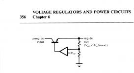
In fact you can argue that this is not really a regulator - it doesn't 'regulate' anything. The output voltage varies with load and there is no mechanisme that feeds any deviation of the output back to some control element to attempt to keep Vout constant.
As Andrew noted, it does have no stability problems, but it's performance is also pretty lame. OTOH, a well designed regulator also has no stability problems.
Jan
Hi Andrew.
Is a sense lead required for Fig 4-1a? Can the NPN and regulator share Vin? My setup would be a single, cap filtered, Vin. My precision regulator does not have a sense lead (just Vin, GND and Vout).
I thought the resistor in a 4-1b and in a Zener setup was there to deliver just enough current to the regulator and transistor base so that it could operate, i.e. just enough to supply the base current and voltage ref, as opposed to "sense".
In fact you can argue that this is not really a regulator - it doesn't 'regulate' anything. The output voltage varies with load and there is no mechanisme that feeds any deviation of the output back to some control element to attempt to keep Vout constant.
Jan
But an open loop regulator still provides input voltage regulation as well as ripple rejection. So in some applications, especially analog audio circuits, this is quite adequate.
In fact you can argue that this is not really a regulator - it doesn't 'regulate' anything. The output voltage varies with load and there is no mechanisme that feeds any deviation of the output back to some control element to attempt to keep Vout constant.
Is this not the purpose of the sense lead? (in 4-1a)
I presume your comment relates to simply using a 3-terminal regulator - without a sense lead - to drive the base of the transistor as per my questions above.
So... no sense lead => use a PNP configuration (a la 4-1b) and deal with stability issues?
If true, the proposal that I use this good regulator to drive an NPN transistor's base would seem to lead to potentially significant shortcomings with variable load?
If you need to use an external power transistor + heatsink to get a sufficiently high current supply, I think the best idea is to go ahead and build a complete regulator. You could do it with a uA723 + NPN power transistor and get current limiting thrown in for free. Or you could use an opamp, NPN power transistor, and a voltage reference IC. The key to success for newbies is to select a high-fT power transistor (D44H11, MJL3281A, or 2SC5171) and a medium-to-low bandwidth opamp (GBW < 2 MHz). The OP07 would be an excellent choice; for the brave and the bold, an NE5534A with external compensation capacitor between pins 5 & 8 will give you a chance to fiddle around and "optimize" while still having an extremely stable feedback control system. Will it measure better than a Jung/Didden SuperRegulator? No. Will it be stable? Yes. Will it measure better than an LM317 with an external power transistor? Yes.
Attachments
Hi Mark. I will take a look at your attachments. The proposal was in the context of "taking the [current] load off" an existing discrete 12V regulator I have purchased. This regulator is fashioned as a significantly improved, direct, drop-in replacement for TO-220 package IC regulators and I have been using it as such with its FET bolted directly to the finned sidewall of my enclosure. It was suggested that if I am finding the current needs of the 12V rail (which I need to measure) are straining the regulator too much (it failed recently - I suspect due to improper connection to the sidewall but perhaps because of the foregoing) then it may be better to have it drive a transistor such as the 2SC3264. While I wait for the regulator to be repaired to measure the current demands I was trying to understand how I would configure such a combination plus understand what's gained and lost from moving in this direction (see the last question in my original post).
I'd love to get to the point of doing my own regulator from scratch but I have a lot to learn. Hence starting with my little LM317 / SPX431 learning exercise to which I owe a response to your last post.
Thanks for the help (and patience)
I'd love to get to the point of doing my own regulator from scratch but I have a lot to learn. Hence starting with my little LM317 / SPX431 learning exercise to which I owe a response to your last post.
Thanks for the help (and patience)
Is this not the purpose of the sense lead? (in 4-1a)
I presume your comment relates to simply using a 3-terminal regulator - without a sense lead - to drive the base of the transistor as per my questions above.
So... no sense lead => use a PNP configuration (a la 4-1b) and deal with stability issues?
If true, the proposal that I use this good regulator to drive an NPN transistor's base would seem to lead to potentially significant shortcomings with variable load?
Correct, I didn't realise that is the sense for the regulator, so it will drive the pass transistor to regulate the output.
Jan
- Status
- Not open for further replies.
- Home
- Amplifiers
- Power Supplies
- Series Pass Regulators driven by 3-terminal regulators