my first post here,I am doing some push pul subs with 2 10' boston drivers and have everything in place I just need to know the wiring of speaker to speaker ,series or paralell ,my thinking is paralel so one speaker will push as the other pulls at the same time.is this correct or can someone help me out here .this is a first time project and i am not real experienced in this.here are pictures so far at my photo bucket
Subwoofer Bic Project Photos by cleonjr | Photobucket
Subwoofer Bic Project Photos by cleonjr | Photobucket
ok I think i can make this simpler,I have installed the speakers 2 10" boston acoustics 6 ohm each in a subwoofer box with 2 input terminals each speaker is wired with correct polarity to each terminal giving me 2.3 ohms per terminal. ok I am trying to do a push pull sub design.I have coils measuring 7.4mh and another 2.5mh acordintg to the calculator I need a 18mh,do I ??
and I have a 150mfd cap and a 200uf cap I think the 200 will be enough ,is that right.can I get some help with the cut of freq I want to get everything under 100hz.
I can do wiring later I will have 2 subwoofer boxes with 2 10" in each one.hope I am not confusing.please pbe patient with me I am new to this stuff.


Forget using big inductors. Use line level filters or go active.
Is this intended for home use or car audio? Few amps for home use are 2Ω stable, not that there isn't a plethora of amps available (eBay) that can. 4 smaller amps driving each woofer would be better (easier)
Is this intended for home use or car audio? Few amps for home use are 2Ω stable, not that there isn't a plethora of amps available (eBay) that can. 4 smaller amps driving each woofer would be better (easier)
it is for home i am using a technics sa6800x 4 channel reciever I want to use the rear canels for the subs and the front for some BIC lcr ph60 speakers
![URL]](/community/proxy.php?image=http%3A%2F%2F%5BURL%3Dhttp%3A%2F%2Fs905.photobucket.com%2Fuser%2Fcleonjr%2Fmedia%2FSubwoofer%2520Bic%2520project%2FHPIM8974.jpg.html%5D%5BIMGDEAD%5Dhttps%3A%2F%2Fi905.photobucket.com%2Falbums%2Fac259%2Fcleonjr%2FSubwoofer%2520Bic%2520project%2FHPIM8974.jpg%5B%2FIMGDEAD%5D%5B%2FURL%5D&hash=6bc4387dc8e5b00ce33502cbdda17ba8)
![URL]](/community/proxy.php?image=http%3A%2F%2F%5BURL%3Dhttp%3A%2F%2Fs905.photobucket.com%2Fuser%2Fcleonjr%2Fmedia%2FSubwoofer%2520Bic%2520project%2FHPIM8972.jpg.html%5D%5BIMGDEAD%5Dhttps%3A%2F%2Fi905.photobucket.com%2Falbums%2Fac259%2Fcleonjr%2FSubwoofer%2520Bic%2520project%2FHPIM8972.jpg%5B%2FIMGDEAD%5D%5B%2FURL%5D&hash=a0c6f32d7ed1c6e5b9a5cfd3fb2f5023)
![URL]](/community/proxy.php?image=http%3A%2F%2F%5BURL%3Dhttp%3A%2F%2Fs905.photobucket.com%2Fuser%2Fcleonjr%2Fmedia%2FPICTURES%2FHPIM8986.jpg.html%5D%5BIMGDEAD%5Dhttps%3A%2F%2Fi905.photobucket.com%2Falbums%2Fac259%2Fcleonjr%2FPICTURES%2FHPIM8986.jpg%5B%2FIMGDEAD%5D%5B%2FURL%5D&hash=ea764f62250ecf2655690aa98b190f56)
If you connect both woofers with the same polarity, one will push air into the room while the other pulls it out of the room. The result will be no sound.
You have to wire them out of phase, i.e. plus terminal of one woofer connects to minus of the other and vice versa, if you use them parallel. Minus to minus and each plus to one side of the amp, if you use them in series.
I am not sure, whether the manufacturing tolerances on Boston woofers are tight enough to recommend series connection. On the other hand, for a passive crossover it is preferable, because you need coils of half the size (value). It is also better for the amp.
The issues with passive subwoofer crossovers are the component size and resulting prices, and the vicinity of crossing frequency and driver resonance. Greebster's advice to use active filtering is absolutely right, as is the recommendation to use separate amps per driver.
it is going to have to be passive,can I do 2 coils in series ,say 2 8mh with a 200uf cap wired in a kobel design
One driver in each enclosure will need to be reverse polarity wired as pacificblue mentions. You could only use that receiver if the speaker drivers are wired in series eg 6Ω+6Ω = 12Ω.
it is going to have to be passive,can I do 2 coils in series ,say 2 8mh with a 200uf cap wired in a kobel design
An externally hosted image should be here but it was not working when we last tested it.
Using old school receivers is going to be an issue. If it has Pre Out/ Main In then using passive line level might be the way to go. If not, then either using something better fit for the job is required or modify the existing.
First order filters are rarely adequate for the job, far to much upper range will still shine through. Also the cost of quality parts for a better 2nd order or greater filter will just add up to even more.
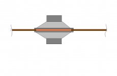
When one speaks of the "Push-Pull effect it is referring to an Alignment which has two drivers face to face, the small volume between the drivers is sealed. The two cones interact with each other (Both are 'traveling' in the same direction) ..the two cancel out any Non-linearities of any one. "Isobaric Push Pull" is the correct term.
___________________________________________________Rick.......
___________________________________________________Rick.......
Attachments
Not at all. Still wired the same. Wired; AMP + to Speaker facing "normal" + terminal. Negative - terminal of the "normal" speaker is then wired to the Negative - of the reversed speaker and it's positive is then connected to the AMP - terminal.but wired in series i will defeat the push pull efect wont I?
I am going to have to figure something,I have a technichs suv8x amp it has pre out's will I still be able to use the Bics like I want to and keep the subs on their own chanell.
When one speaks of the "Push-Pull effect it is referring to an Alignment which has two drivers face to face, the small volume between the drivers is sealed. The two cones interact with each other (Both are 'traveling' in the same direction) ..the two cancel out any Non-linearities of any one. "Isobaric Push Pull" is the correct term.
___________________________________________________Rick.......
This is nothing more than a push pull acoustic suspension speaker. It lacks equal pressure due to the rather larger space between drivers. The major advantage of this design is reduction of the second harmonic distortion.To do properly we would be required to double the enclosure volume for two drivers. Whereas Isobaric this volume between drivers is very little and the enclosure volume is halved.
When one speaks of the "Push-Pull effect it is referring to an Alignment which has two drivers face to face, the small volume between the drivers is sealed. The two cones interact with each other (Both are 'traveling' in the same direction) ..the two cancel out any Non-linearities of any one. "Isobaric Push Pull" is the correct term.
___________________________________________________Rick.......
there are some that are not face to face m&k makes some as does dali.I thing B&w did to,I know Isobaric and that is totaly different than I want.
I think I am going to have to go with a series 12 ohm setup ,can I get some help with a LPF that will cut off at 100hz
told you guys I am not well versed in this stuff but I catch on quick,thank you for the help ,I really need it!!
Getting the relative polarity right is independent of whether they are wired series or parallel. Parallel would be better if the impedance didn't get so low. Series will allow some electrical interaction between the drivers since their impedances won't be identicle over frequency due to acoustic variations, but that may largely cancel out.
Active biamping is a huge improvement, but then you've got to buy or build a 4 pole active crossover. The proper topology for a low pass passive crossover would be a coil in series and then a cap to ground. The formulas are on the web. For such a filter to work correctly, you need to know the impedance of the drivers at the frequency you want to roll them off at. It could be way different than the nominal ohms rating.
Active biamping is a huge improvement, but then you've got to buy or build a 4 pole active crossover. The proper topology for a low pass passive crossover would be a coil in series and then a cap to ground. The formulas are on the web. For such a filter to work correctly, you need to know the impedance of the drivers at the frequency you want to roll them off at. It could be way different than the nominal ohms rating.
Getting the relative polarity right is independent of whether they are wired series or parallel. Parallel would be better if the impedance didn't get so low. Series will allow some electrical interaction between the drivers since their impedances won't be identicle over frequency due to acoustic variations, but that may largely cancel out.
Active biamping is a huge improvement, but then you've got to buy or build a 4 pole active crossover. The proper topology for a low pass passive crossover would be a coil in series and then a cap to ground. The formulas are on the web. For such a filter to work correctly, you need to know the impedance of the drivers at the frequency you want to roll them off at. It could be way different than the nominal ohms rating.
Ok Bob,thats why I am using the 4 channel reciever ,I want to use it kinda like a bi-amp situation.with left and right rear channels for the two subwoofer boxes.how fould I figure out the impedence at the rolloff I want?
ok so I have come up with ,I am going to have to live with 10 ohms with both 10" wired in series,ok so the calculations I come up with for a inductance is 24mh and a cap 228uf ,and the coil is in series + + and the cap is after the coiland grounded + - is this correct to finish the sub.
- Status
- Not open for further replies.
- Home
- Loudspeakers
- Subwoofers
- series or parallel