I have confused myself as to the proper way to connect two identical film capacitors in series with regards to outer/inner foil direction in a loudspeaker crossover application. Please see attachment. I'm doing this because I have lots of the capacitors and I need a value exactly half the capacitance. I'd appreciate any guidance as to the proper option listed. Thanks
Attachments
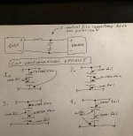
Connect the outer foil ends together (as in #2), and use the other ends for the connections to the crossover.
Then they can be mounted side by side without interaction. This is not very critical, though.
Then they can be mounted side by side without interaction. This is not very critical, though.
Last edited:
Machs Nichs. Makes no difference for nonpolarized caps. The AC those caps are sourced with goes in both directions anyhow. How could one polarity be any better than the other?
Capacitors on a schematic, or capacitors modeled with mathematics, are not the actual capacitors in the physical circuit.
Those are wire, plastic, metal foil, chemicals, etc. that are assembled to approximate an ideal capacitor. Each different
assembly will have particular strengths and weaknesses, and may be more, or less, suitable for any particular application.
A wound film capacitor has an outer foil and an inner foil, and if the outer foil is connected to a fixed potential,
or a low impedance circuit node, the inner foil will be shielded from external fields due to nearby components,
board traces, etc. This can be important, particularly in high impedance circuitry and on crowded pcbs.
Where To Connect the Outside Foil on Capacitors
Last edited:
With the crossover schematic as presented in post #1, there is no advantage at all.
For a start in the crossover schematic presented, the signal level applied will be in the volts, not in millivolts or microvolts for that matter, so noise injection into a capacitor is of little consequence in this application.
The band sometimes seen on a capacitor was to signify the outer foil connection where the capacitor was used as a bypass capacitor, and thus this terminal was grounded to the chassis. This helped to minimize induced noise in high impedance valve circuitry, but not so if used in the signal path.
C.M
Machs Nichs....How could one polarity be any better than the other?
If you turn it the wrong way, the music will be reproduced up side down/backwards. No?
- Home
- Loudspeakers
- Multi-Way
- Series Capacitor foil orientation in crossover