I am looking for a simple circuit that will supply 6.3 V to two valve heaters. In order to keep current consumption to a minimum, it circuit needs to supply the heater current in series.
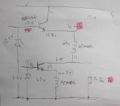
It's been a long while since I dabbled with analogue circuits, but below is what I have come up with. Transistor base is kept at a fixed voltage using a zener;
the heaters receive Ic + Ib; there is a shunt resistor to take the Ib from the top transistor. The circuit is not complete as there will be resistors for the zener and base as well as capacitor for smoothing.
The supply to the circuit is 12 V AC rectified so the snag may that there is not enough voltage for the circuit.
Comments and alternatives welcome.
Attachments
If semiconductors are allowed in this design, I would use a low drop linear regulator such as the LD1084V. It greatly reduces the number of parts required and it only needs about 1.5V of drop. This will fit your application, provided that you use a oversized transformer. Be sure to choose a part that will withstand the valve heater inrush current. LD1084V does work up to 5A and is cheap. The alternative is a switching regulator.
Yes. Identical valves (tubes), 6J1, heater voltage 6.3 V.
Semiconductors are allowed. 🙂
I would like the supply to be regulated and limited current hence why both heaters are in series.
Semiconductors are allowed. 🙂
I would like the supply to be regulated and limited current hence why both heaters are in series.
If you want a regulated supply, use an ultra low dropout regulator on a heatsink. You have a 12V winding, so you should have plenty of voltage available for that.
In my opinion, this is potentially a waste of time. Put a bridge of schottky diodes off the secondary of your power transformer with a resistor input type power supply. Dial it in to get as close to 12.6V as you can and call it good!
In my opinion, this is potentially a waste of time. Put a bridge of schottky diodes off the secondary of your power transformer with a resistor input type power supply. Dial it in to get as close to 12.6V as you can and call it good!
I do like DC heaters, but I have to point out that 2 6.3V heaters in series will work fine off a 12VAC supply, no components of any kind needed at all.
A very good comment. Yes, reducing unneeded complexity is always good !I do like DC heaters, but I have to point out that 2 6.3V heaters in series will work fine off a 12VAC supply, no components of any kind needed at all.
I think you could do something similar to your circuit, but just put the two heaters in series and use a single transistor.
I would go the 12VAC heaters route too.
I haven't found DC heaters to be any better than AC heaters.
I have always found the hum came from a different source like bad layout.
Keep it simple if you can.
I haven't found DC heaters to be any better than AC heaters.
I have always found the hum came from a different source like bad layout.
Keep it simple if you can.
...a simple circuit...
Attachments
The circuit originally shown appears to contain a fundamental error: it tries to set both the current and voltage, which can only work if they perfectly match what the components in question (valve heaters in this case) actually want.
The series current arrangement means that the heater currents are constrained to be more or less equal (apart from BJT base current). Yet there are separate voltage settings, coming from two different zeners and Vbe drops.
For valve heaters you can set voltage or current or some linear combination of the two; you cannot set both. For two similar (nominally identical) valves if you want series heaters then just wire them in series and apply 12.6V DC or AC. Job done.
^^^^^^
Plus each regulator needs WAY more than 0.2V drop to regulate; voltage drop will be larger than that even when NOT regulating but simply saturated.
You need to:
1) put both filaments in series, period.
Being same type and rating, they will inherently self balance, within the tolerance set up by the valve manufacturer himself.
2) then just use *one* regulator, discrete or integrated (or even passive CRC filtered) to supply 12.6V to the heater string.
- Status
- Not open for further replies.
- Home
- Amplifiers
- Tubes / Valves
- series 6.3V power supply to valve heater