Hello, could you tell me why it should not be desirable to use a serial LC filter on a low Q subwoofer in order to use it in a dipole configuration ?
The main advantage it that the subsonic register is still damped and the drawbacks are inaudible if the center frequency is under 30Hz.
Why please ?
The main advantage it that the subsonic register is still damped and the drawbacks are inaudible if the center frequency is under 30Hz.
Why please ?
You mean combining a rumble filter with the low pass, but at the same time using the resonance to match the dipole rolloff?
Should this be in Line Level?
Should this be in Line Level?
Yes, i'm already using it in the line level and i'm dubitative if it would be doable or not with a large ferrite coil.
It gives the large bass reflex cabinets impact in the infrasonic region without the physical and material drawbacks habitually encountered, the impacts are contained in the NF like encapsulated detonations.
It gives the large bass reflex cabinets impact in the infrasonic region without the physical and material drawbacks habitually encountered, the impacts are contained in the NF like encapsulated detonations.
Last edited by a moderator:
Finding a suitable higher value inductor with a high enough self-resonance takes some work, if that's what you mean.
It is a part of the problem but i'm a tad anxious about the ability of a class D amplifier to handle such large a mount of inductance and capacitance.
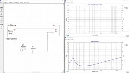
Here is an exemple with the 18PS100 with a LC :


Attachments
Last edited:
Am I reading this right? Straight, the sensitivity is about 95; but with the L-C tank, more like 65? If dB SPL, the 30dB loss of sensitivity is likely to require 1,000 times as much amplifier power. Although not really power: excess voltage in the inductor reactance.Here is an exemple
IMO, huge EQ like this is best done before the power amp. Even then the 30:1 added voltage gain is liable to bring up system hiss.
Yes, you are right it is impossible, so i'm triyng to perform it with an opreational amplifier on the Line Level, but i'm bubitative with the TI simulation that recommand a TLV2401.Am I reading this right? Straight, the sensitivity is about 95; but with the L-C tank, more like 65? If dB SPL, the 30dB loss of sensitivity is likely to require 1,000 times as much amplifier power. Although not really power: excess voltage in the inductor reactance.
IMO, huge EQ like this is best done before the power amp. Even then the 30:1 added voltage gain is liable to bring up system hiss.
Attachments
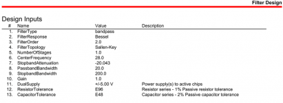
Slew rate (Typ) (V/us) 0.0025 V/us (is it a problem from 0 to 1Khz ?)
Noise 500 nV/√Hz (it seems very good ?)
Noise 500 nV/√Hz (it seems very good ?)
This is typical of a passive EQ for a dipole system - you cannot really boost power in the transfer function so the only alternative is to apply a huge amount of loss (cut) to flatten the low frequency response.Am I reading this right? Straight, the sensitivity is about 95; but with the L-C tank, more like 65? If dB SPL, the 30dB loss of sensitivity is likely to require 1,000 times as much amplifier power. Although not really power: excess voltage in the inductor reactance.
View attachment 1034958
IMO, huge EQ like this is best done before the power amp. Even then the 30:1 added voltage gain is liable to bring up system hiss.
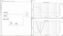
By choosing the LF cutoff to be very low (around 25Hz) with a low Q driver the OP has prescribed how much loss will occur. There is no way around it really. By choosing a higher LF cutoff you can reduce the losses that must be used to flatten the response. Inevitably the system will be very low efficiency, but that is the nature of the beast with dipoles at LF.
This is a good example of why dipole bass implementations that combine a low Q driver and passive EQ have some downsides. A high/higher Q driver will display much better in-air voltage sensitivity down to Fs. Even if its passband sensitivity is lower, near Fs the sensitivity will be higher.
Although it would not apply when using a passive network, there is a trick to overcoming the driver's poor LF efficiency (to some extent): if you combine very high Bl, low Q drivers with class D amplification the back EMF from the driver at LF returns energy to the output inductor of the amp, which has the effect of putting energy back into the PS (sometimes this is called bus pumping). The result is that, overall, the actual (or "true") power consumption by the driver is actually very low, although you need very high voltage to drive it. Keele published a paper on this a few years ago, and I found it fascinating. I didn't believe it at first until I did some modeling. I have attached a copy of Keele's AES convention presentation preprint on the subject from 2003.
Attachments
Way-way-way-down. Thermophone efficiency. About like propelling a cargo ship with a teaspoon for an oar.low Q driver and passive EQ have some downsides.
The Q is not even the point. Below resonance it is all about the Bl and the useful air paddle. Not just the cone area but also how much air can slosh around the cone. A popular-price woofer without a box or even a real baffle is throwing the game before it starts.
And yes, Keele is the high priest of open back. His older paper (the one with his face in the hole) points out that cheap low-Q drivers may be useful in open array. But "Q" only has meaning very near resonance. Q*Fs is a more useful metric for fast figuring.
FYI: "bubitative" sure is an English word but I have never seen it used. I too am doubtful about the TLV2401 here. It may actually be OK, beause you do NOT want any high frequencies. But a TL072 would be fine also. And those impedance values are not real-world. Transpose to 100 times higher impedance for less loading on the source and opamp, less costly capacitor values.i'm bubitative with the TI simulation that recommand a TLV2401.
100 times higher impedance, witch impedance are you talking about ?FYI: "bubitative" sure is an English word but I have never seen it used. I too am doubtful about the TLV2401 here. It may actually be OK, beause you do NOT want any high frequencies. But a TL072 would be fine also. And those impedance values are not real-world. Transpose to 100 times higher impedance for less loading on the source and opamp, less costly capacitor values.
Do you mean GBW ?
100 times higher impedance, witch impedance are you talking about ?
- Home
- Source & Line
- Analog Line Level
- Serial LC filter on a low Q subwoofer in order to use it in a dipole configuration