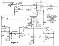
Can someone explain to me why there are two pots for frequency adjust on any parametric EQ schematic I look at? At times I think they may be the same pot, but nonetheless, I'm still confused since there is only one Boost/Cut pot.
Am I reading the schematic wrong? I've attached a schematic for reference. Are there actually 2 pots for frequency? Are there 2 pots for Bandwidth, as well?
Thanks in advance!
Am I reading the schematic wrong? I've attached a schematic for reference. Are there actually 2 pots for frequency? Are there 2 pots for Bandwidth, as well?
Thanks in advance!
Attachments
Hi,
They are usually dual pots (stereo) when you need to adjust two
resistances at the same time and single (mono) when you don't.
rgds, sreten.
They are usually dual pots (stereo) when you need to adjust two
resistances at the same time and single (mono) when you don't.
rgds, sreten.
I kind of figured it was something like that. I only need a mono installation, so I'll omit one of the circuits for the second freq. adjustment.
Thanks much for the replies! 🙂
Thanks much for the replies! 🙂
Um...
He called the pot a "stereo" pot, meaning two separate sections that have a common shaft. The circuit you posted is not stereo.
To change the frequency of these tuned circuits, you need to change more than one resistor value, hence the dual section pot. There is only one frequency adjustment here, but it requires changing resistance at two points.
Um...
He called the pot a "stereo" pot, meaning two separate sections that have a common shaft. The circuit you posted is not stereo.
To change the frequency of these tuned circuits, you need to change more than one resistor value, hence the dual section pot. There is only one frequency adjustment here, but it requires changing resistance at two points.
After I replied, I looked at the schematic again and realized it's not stereo, and got confused again as to why there are 2 freq adjust pots. Then you (Enzo) gave me the idea that each freq adjust can be calculated differently.
I've attached another schemo for review. This one makes a little more sense to me since there are 2 separate pots for Boost/Cut.
Here's what I'm thinking:
-U2a- Low mids
-U2b- High mids
Does this make sense? What do you think?
Attachments
- Status
- Not open for further replies.