Yes, it's about getting the filtering frequency of the coupling capacitor a decade, or more, beyond the audio band. If it's an electrolytic then add another one or two octaves beyond the decade.
i.e. for a 100k, then a plastic film coupling capacitor of 1uF would do, or use a 4u7F electrolytic
you can see that for 10k, then we have 10uF plastic or 47uF electro
for 2k use 220uF electro.
and for the D.Self example of 1k use a 470uF
i.e. for a 100k, then a plastic film coupling capacitor of 1uF would do, or use a 4u7F electrolytic
you can see that for 10k, then we have 10uF plastic or 47uF electro
for 2k use 220uF electro.
and for the D.Self example of 1k use a 470uF
The point is that the load isn't anywhere close to 1k here, as should be plainly obvious from the schematics given. As suggested, we're talking 10k, or 47k as shown above (plus ~120 ohms (give or take) of source impedance). Even when taking potential capacitance mismatch into account that might reduce low-frequency CMRR (bonus points for 5-10% tolerance parts or hand-matching), 100µ seems plenty big enough.
You are right. Only wanted to show what may have been the reason to use 470µF. D.Self mostly uses 100µF/35V BP in input stages with 50k impedance.
BR, Toni
Self states clearly that bigger is better. At any rate, the idea was for the board to be able to accommodate a cap of that size. If someone wants to insert a lower value cap that's readily done.
I take on board the suggestion regarding the resistors. That can be an amendment for a future iteration of the board if there is one.
I take on board the suggestion regarding the resistors. That can be an amendment for a future iteration of the board if there is one.
I'll bet if you measure the leakage of the 470uF nonpolar electrolytics that you haven't yet stuffed and soldered, you'll find it's waaaay less than 0.1 microamps.
Easiest way to do so is to haphazardly slap together a transresistance amplifier made from a low Ibias opamp, namely an FET opamp, on your solderless protoboard. This lets you try any and every bias voltage you might wish. 15 minutes of your life.
Pick the transresistance R=1Meg ; or if you are feeling timid, R=100K.
_
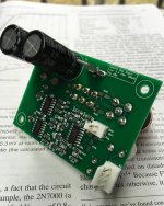
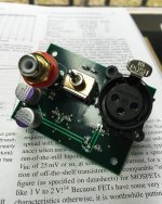
Attachments

It seems that the second manufactured version (ver 2.4) referenced in post 111 has passed "ASTX certification" with flying colours. Toni mentioned to me by email:

PS: I have a few spare PCBs which I can make available at my cost
I get noise down to -132dB A weighted referred to 4 Vrms RCA input - my measurement limits.
PS: I have a few spare PCBs which I can make available at my cost
What is "ASTX certification" ?......has passed "ASTX certification" with flying colours.
PS: I have a few spare PCBs which I can make available at my cost
What price for the pcb's ?.
Dan.

Dan - it was a bit of a joke. DIYAudio member 'astx' i.e. Toni tested the boards.
Mark, should be ok now.
Mark, should be ok now.
Last edited:
This may be a dumb question but I have a query regarding 0 Ohm resistors. I have some 1206/3216 0 Ohm 'thick film resistors'. In this circuit I have been using thin film resistors due to their superior noise characteristics. At the output of the circuit (see post 111) are resistors R27 and R28 which provide a placeholder for a voltage divider at the output. I want to jumper R27.
Are 0 Ohm thick film resistors actually thick film, in which case I need to find a thin film equivalent or other form of jumper (e.g. a very short piece of solid copper wire), or are they merely a piece of solid wire in that package in which case, with convenience prevailing, using one to jumper R27 would be just fine?
Are 0 Ohm thick film resistors actually thick film, in which case I need to find a thin film equivalent or other form of jumper (e.g. a very short piece of solid copper wire), or are they merely a piece of solid wire in that package in which case, with convenience prevailing, using one to jumper R27 would be just fine?
The 40 ver 2.4 PCBs (10 panels of 4 boards each) I had produced cost me £6 each once I factor in the cost of production, shipping, duties and the first draft which was binned after it performed badly in testing.
I will therefore offer them at this price per board (plus P+P which will obviously depend on where the recipient lives).
I will therefore offer them at this price per board (plus P+P which will obviously depend on where the recipient lives).
I'd also like to say a big round of thanks to Toni. He conducting tests on both the first and second version boards. After a discussion regarding typology he pushed me to redo the routing, use the larger resistors and fix the supply bypassing. He also pointed out that I had the toggle switch back to front! (It didn't occur to me that a toggle switch wouldn't activate the pins the toggle was pointing to...)
So anyone who uses these boards owes Toni a big thank you also!
So anyone who uses these boards owes Toni a big thank you also!

I've been doing further testing of this board. One thing which came out of my attempts to measure its noise is that it needs a minimum load. It doesn't need much of a load - I tested a 10k resistor across the output and all seemed fine - but I would recommend that R28 be populated with, say, circa 2k resistor assuming R27 is jumpered/shorted. (See post 111 for circuit.) If anyone uses a voltage divider on the output the resistor values will need to be recalculated. 2k is easily driven.
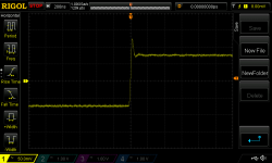
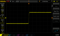
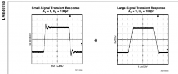
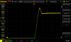
I have also looked a little more at whether the 27p caps can be removed. Attached pic 1 shows a transient reaction to a 150mVpp with the caps removed. The 'no cap' waveform is still better than that shown in the data sheet (pic 3). Pic 2 is with the 27p caps in place - the overshoot is gone. I also tested larger transients. Pic 4 and 5 are 15Vpp transient response with caps and pics 6 and 7 is the same but without the caps. The caps dampen any ringing but there's no sign of instability without them. Removing the caps seemed to lower noise but I am still refining my test setup for this - at the moment it is still too variable for this type of work to reliably distinguish between, say, -113dBu and -115dBu as a result of board changes.
I'd welcome thoughts on this.
Attachments

No thoughts on whether the caps are necessary/ideal?
The extra noise without caps sound logical; without the caps, the noise gain goes up with frequency, and can ultimately lead to instability.
It *may* be OK in your setup without, but you want to be sure it is fine in all different setups, so I believe it is prudent to include the cap. The datasheet value always is to make sure it is stable worst case, also with the spread in opamp production.
But maybe 15p is also sufficient. Have you checked it with lower cap values?
Jan
Hi. It appeared to me that there was lower noise without the caps, but then again my test setup isn't reliably fine enough to distinguish between one or two dBu. That would seem to make sense given less components are in the signal path. I have not checked lower values. I did check 47p.
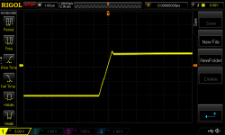
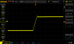
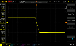
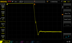
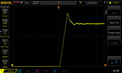
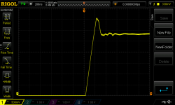
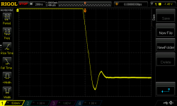
Attached are some pics zooming in on the output waveform from a 10Vpp square wave (much, much bigger than anything this input board would ever have to suffer).
First two are with 27p caps. Second two are without caps. Pics 5 and 6 are with 47p caps. I thought the difference between pic 1 (27p trailing edge) and 5 (47p trailing edge) surprising.
My original implementation of 27p was a rather thoughtless copy of what Self did in Fig 18.9 of Small Signal Audio Design (2nd ed.). But I note now that he was using 27p in conjunction with 10k resistors, leading to a -3dB point of 589kHz. Here, with much lower resistor values, the -3dB point with 27p is way up at 7.2 MHz.
Attachments

- Home
- Amplifiers
- Solid State
- Self's "5532 Low Noise Unity Gain Balanced Input Stage"