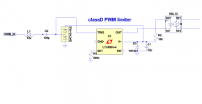
below an idea for a simple limiter consisting of a one-shot and an opto LDR.
the supply is derived from the same PWM stream. the inductor limits the peak current in the diodes and is set to resonate above the max PWM freq.
the oneshot is set at 10usec
the supply is derived from the same PWM stream. the inductor limits the peak current in the diodes and is set to resonate above the max PWM freq.
the oneshot is set at 10usec
Attachments
Last edited:
...promising.
IMHO next relevant step would be a simulation with closed system loop by adding the signal source and power amp and then analysing+tuning of the dynamic behavior of the full system.
And even more promising when you manage to translate it to a solution with the NE555...
Definitely an approach which is worth to examine. Keep on going.
I don't have a dynamic spice model of the nsl32 yet. I simulated an ucd type pwm using a single digital inverter with delay and vhigh and vlow at +/-80V; the LTC retriggerable timer is just easy , lazy and small. I built it on 1cm2. (w/o the inductor and coupling cap).
pict next time .. need to order the NSL32 (farnell) or the faster one RSL-32 RS2 at rs-components germany; strangely not available at rs-components spain. that faster rs2 may need additional time stabilization. i like the natural release time of the ldr cells.
pict next time .. need to order the NSL32 (farnell) or the faster one RSL-32 RS2 at rs-components germany; strangely not available at rs-components spain. that faster rs2 may need additional time stabilization. i like the natural release time of the ldr cells.
found a vactrol VTL52 model that looked OK , only the ac impedance was hosed up by a 100nf cap across the LDR. changed it to 1p. here the sim using a burst with 10% duty and 0.3 amplitude ratio. schematic mostly in behaviourals. the sim time was taking some 6msec for the one-shot to stabilize its output, so I had to trick it not to start in full attenuation. bottom trace is the output saturating at 80V. top trace is the one-shot triggering the opto, and the trace restores undistorted after 1 cycle. this is why we worship ltspice...
I could have simulated this faster by making a one-shot triggering on a threshold set at 95% of the voltage supply on each side. I like the simplified UCD amp behavioural, I found it somewhere on the web.
I could have simulated this faster by making a one-shot triggering on a threshold set at 95% of the voltage supply on each side. I like the simplified UCD amp behavioural, I found it somewhere on the web.
Attachments
555 version
and here is the 555 version; simulates the same; diodes bat40 or the like.
retrig is done by discharging the cap directly from the trig signal. best seems a slow version like the NSL32 not the SR2 or 3. interestingly the ground reference can be any line , gnd, neg vcc, pos vcc. at neg vcc you can combine it with a comparator and reference to sense the current in the bottom PWM fet for further overload lowZ protection.
Attachments
Charming simple 😎
From the parameters in your schematic I find a 3kHz signal repeating every 10ms, means you are assuming the DJ to play music with 6000 beeps per minute 😛
That's a panic disco, nothing for old men...
Uncompressed the 3V input would try to chase the poor amp to 96V and the limiter reduces it to 80V. Really nice.
Does it also show such nice behavior at different input levels i.e. 3V and 5V and also different signal frequencies and repetition rates without needing to adjust any component values?
In my solution the challenge was to let the limiter behave well over a wide range of different input levels and finally forced me to settle a PD loop regulation characteristic, while allowing different signal frequencies and repetition rates was simple.
P.S.
Your description of the Vactrol model appeared somehow familiar - I guess I used the same model from the WEB in my limiter simulations.
Spice Component and Circuit Modeling and Simulation
actually I changed/cheated the recovery time of the vactrol to speed up simulations. I had 17Gb output on a 10ns max timestep total 200msec sim. took a few hours on a 6-core intel. the dynamics could be run simpler by triggering a oneshot or compare on either end of the amplitude. the nice thing is that the one-shot triggers before actual clipping occurs. I'll redo the sims this way ..
tjsak-boom dynamics
this is a behavioural of the vactrol plus the one-shot implemented as a simple . window detector. I don't trust the actual dynamics; especially the attack time is no properly modeled. I found the file on www.fullnet.com/~tomg/VTL5C2.ZIP
remove the 100nf across the ldr ...
anyway feel free to goof around with this schematic .. play with the params ..
Attachments
- Status
- Not open for further replies.
- Home
- Amplifiers
- Class D
- self powered limiter for classD