Hello cwtim01, I would like to read the users manual of that DIY Curve tracer to find out
- Can I export the (I,V) data to a file that other software can read? .csv? .txt?
- What is the resolution of the data? 8 bits? 12 bits? 16 bits?
It would seem to be very important to regulate the die temperature when making these kinds of measurements. Do people worry about this?
It would seem to be very important to regulate the die temperature when making these kinds of measurements. Do people worry about this?
Sure. That's the entire raison d'être for companies like Thermostream who sell products to do exactly that, in high volume semiconductor testing.
At home the easy trick is to program your curve tracing software to keep the DUT disconnected from the power supplies, 99% of the time. Datasheets call this "pulse testing" ... you and I call it duty cycle < 1%. For every point on the I-V curve, enable the D/A and A/D for 1 msec, let it settle, make the measurement, and then disable everything and let it cool off for 199 msec before measuring the next datapoint. All the while blowing the DUT with your homemade jerry-rigged Thermostream clone.
The good news is, die self-heating is reduced by more than 200X. The bad news is, an I-V sweep is SLOW. If you sweep VCE from 0V to 20V in 0.1V steps, and then step Ibe from 0 to 10mA in 1mA steps, that's (201 x 11) = 2211 measurements. At 5 measurements per second, 442 seconds. Seven and a half minutes.
If you're REALLY paranoid you can build a work-to-do list containing these 2211 measurements, and then scramble the ordering. Take the measurements in the scrambled order (pausing 199 msec between measurements!) and save the data. Scramble the ordering a second time, take the measurements a second time, and save them. Continue scrambling N times for whatever value of N pleases you. Finally average the data. This ensures that the "thermal history" immediately preceding each datapoint, is random. High-current, high voltage datapoints are not sequential (as they are in a conventional curve tracer's I-V operation).
Last edited:
Hello cwtim01, I would like to read the users manual of that DIY Curve tracer to find out
Would you please tell me the link where I can download and read the user's manual? Thanks a lot!
- Can I export the (I,V) data to a file that other software can read? .csv? .txt?
- What is the resolution of the data? 8 bits? 12 bits? 16 bits?
Hi Mark,
The data is in plain text format and can be easily imported into Excel.
The data is measured by an ADC but I don't remember the chip being used so not sure about the resolution. I'm currently out of town but will check that when I'm back home tomorrow, I believe it's mentioned in the user manual.
The manual comes with the software that the seller sent by email, if you could PM me your email address, I'll send you that when I'm back home.
Thanks and regards.
Last edited:
matching of drivers and outputs is not very important.I have measured one of those at around 1nV/rtHz. It was driven from a low impedance so I didn't bother about current noise, and I didn't measure the 1/f corner either, but still pretty good for a part mostly used for switching...
They're really really slow, though.
The global feedback attenuates the distortions added by the output stages and in the LF region these generally become very low.
But there is one area where hFE matching becomes important.
The driver base current is extracted from above the Vbe multiplier and re-inserted below the multiplier.
If the two driver base currents are identical, all the time, then the multiplier passes the VAS current less the driver base current.
But is not what happens.
The drivers while quiescent generally draw different base currents. This makes the VAS current not equal to the current sink's current.
The more unmatched the quiescent driver base current the worse this becomes.
In addition the drivers do not draw a constant base current. it varies with signal current. This can reach the extreme in the overload condition of one driver pulling no base current and the other passing high base current.
High driver hFE helps, as does driver hFE matching.
The outputs also affect the driver base currents. Matching of output hFE helps.
...
...
- Can I export the (I,V) data to a file that other software can read? .csv? .txt?
- What is the resolution of the data? 8 bits? 12 bits? 16 bits?
The ADC chip being used is ADS7871, which is capable of 14-bit resolution. The data is then save under floating point format in text files, attached an example of the measured data of a 2SJ56.
Attachments
Thank you, cstim01!.. data is then save under floating point format in text files, attached an example ...
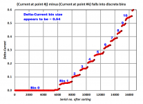
I fiddled with that text file a little bit. To my surprise, the floating point data are NOT quantized as discrete (integer measurement) / (integer scale factor) points. Instead the data fall into rather fuzzy bins with lots of sub-LSB dither / noise. Here are a couple of plots.
The horizontal stepsize, which the internal comments label "Vgs", seems to be quantized in steps of 50 millivolts ... plus or minus some fuzz.
The vertical quantization, which the comments label "Id", seems to be 0.54 milliamps ... plus or minus rather a lot of fuzz. The number "0.54" is itself rather surprising, since it's not a power-of-ten divided by a power-of-two as you'd expect from a binary ADC. All very interesting!
I encourage other readers to download that .txt file and play around with it; you may wish to view the data from a different angle than I did.
_
Attachments

..."Vgs", seems to be quantized in steps of 50 millivolts ... plus or minus some fuzz ...The number "0.54" is itself rather surprising ...
Vgs change of 50mV is the step I specified in the software, but the actual values are measured by the ADC and hence the fuzz I believe. The current are computed by voltage measurement divided by resistor in use (relays are used for different resistors), hence the unusual value.
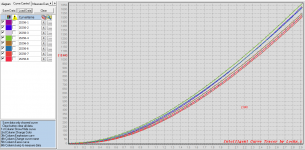
I forgot to mention that file was actually for a set of 8 2SJ56, attached is the graphs from the software. Also attached is the hardware manual, which explains everything in details.
Attachments
I use mpsa42/92 for LTP and CCS and CM and Vbe multiplier.
I use mje340/350 for VAS and CCS.
If I need drivers I use mje15030/31
I use mje340/350 for VAS and CCS.
If I need drivers I use mje15030/31
- Status
- Not open for further replies.
- Home
- Amplifiers
- Solid State
- Selection rules for input and driver BJTs?