Hello,
I picked up a little 10w Ross RG10 pratice amp i might and discovered the same pcb seems to be used for the 25 RGR reverb version so Im going to build in the reverb driver circuit.
problem is I dont know what tank impedance's the circuit requires or if it could be adjusted to suit one of the spring tanks i already have?
Im more good with the mechanics of things, not so good the maths and formulas so if some one could have a glance at the RGR 25 schematic and make any suggestions to what the impedance's would be for the in/out on the tank and weather the in/out should be grounded or isolated rca's that would be great, thanks
Attachments
Last edited:
Those two plans have similar preamps but very large differences.
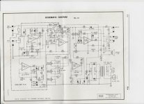
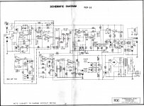
Top right: RG10 has a chip (triangle) power amp; RGR25 has a 7 discrete transistor power amp.
Bottom right: RG10 has a single-rail supply, RGR25 has a dual-rail supply (drawing could be more obvious).
What evidence do you have that *your* PCB has holes for reverb circuit?
Top right: RG10 has a chip (triangle) power amp; RGR25 has a 7 discrete transistor power amp.
Bottom right: RG10 has a single-rail supply, RGR25 has a dual-rail supply (drawing could be more obvious).
What evidence do you have that *your* PCB has holes for reverb circuit?
sorry your right, i didnt even look at the Ross rg10 schematic. it was the 15 watt version that had the reverb as an option. I was looking at photos of the pcb's online because i picked up the 10watt version cheap to save building another reverb driver and ps. I hadnt had a close look at it yet......... scrap this idea,Those two plans have similar preamps but very large differences.
Top right: RG10 has a chip (triangle) power amp; RGR25 has a 7 discrete transistor power amp.
Bottom right: RG10 has a single-rail supply, RGR25 has a dual-rail supply (drawing could be more obvious).
What evidence do you have that *your* PCB has holes for reverb circuit?
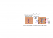
i done this layout for a reverb driver a few years back so will probably just build another.
Attachments
- Status
- Not open for further replies.