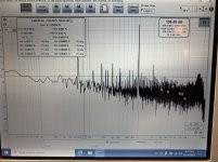
These measurements were taken at an output voltage of ~2.8V, 1000 Hz sine wave, no load.
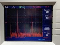
The first in REW on my laptop through the internal sound card. The second is my Tektronix 2012. Neither are ideal, I know, but I don't think that affects what I'm seeing.
On the computer, there is a strong second harmonic (setting the THD), and the third+ are buried in the noise.
On the scope, the third harmonic is dominant, just 10 dB lower than the fundamental, while the second is half as high.
I understand the noise, and the lack of resolution, and all of that, but shouldn't the overall picture be more or less the same? These readings were taken simultaneously off the same output
Attachments
What does the laptop's loopback look like?
Can you go into more detail how you got the Tektronix's FFT plot? Is it just the FFT of the amp's output waveform?
What's the input waveform? Same amplitude for both measurements?
Can you go into more detail how you got the Tektronix's FFT plot? Is it just the FFT of the amp's output waveform?
What's the input waveform? Same amplitude for both measurements?
What does the laptop's loopback look like?
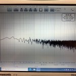
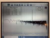
Attached is laptop loopback with no output, and loopback with the same 1KHz signal (aptitude is approximate).
Can you go into more detail how you got the Tektronix's FFT plot? Is it just the FFT of the amp's output waveform?
The Tektronix plot is simply the units FFT function applied to the amplifiers output waveform, adjusted to a useful vertical/horizontal window.
What's the input waveform?
The input waveform is from the laptop, amplitude adjusted upward until ~2.8V was achieved at the amplifiers output.
Same amplitude for both measurements?
The amplitude was the same for both measurements. In fact, both measurements were captured simultaneously, with probes connected to the amplifier output going to the Tektronix and the PC. Disconnecting one or the other did not seem to alter the result.
Attachments
Did you drive the scope into hard clipping, or so soft that only the LSB toggled? A symmetrical square wave has a third harmonic distortion of about -9.5 dB (-20*log10(3) dB to be precise), your -10 dB is quite close to that.
Oooh, I like your square wave/clipping theory. I have not verified that I was not clipping on the scope. And that would explain some other behavior I’ve seen… Would I retain the rest of the signal in that case? I assumed clipping would be more apparent, visually.
What is “LSB”?
What is “LSB”?
Least significant bit. It must be a digital scope, if its noise is insufficient to dither it, a much too small signal can also get grossly distorted.
Ahh, of course. When I drop the amplitude way down the display just drops into the noise you can see at the bottom.
The clipping bit crossed my mind too. Being able to see 2nd and 3rd harmonics on a scope just via FFT would require tremendous THD.
I rechecked with careful eye to output voltage. Turns out I *was* causing clipping on the scope. With the output voltage set to 2.5v I reran the FFT test and was able to observe a clear second and third harmonic, and observe changes to them as I adjusted P3!
One thing that seemed odd to me was that, while I could find the minimum H2 in the middle of the dial, and maximums on both ends, H3 simply followed H2, remaining about 10-15 dB below it whatever the value of H2. I was expecting them to switch between being the larger magnitude.
I'm aware of this limitation. However, I was able to see clear bars at 2x and 3x my fundamental frequency. This would seem to indicate that I have enough resolution to observe both the 2nd and 3rd harmonics. Is that not necessarily the case? Would the resolution of the scope be showing me erroneous data? I assumed I simply wouldn't see one or both of them, or they would be obscured by noise*, if my resolution wasn't high enough.
*Obscured by Noise is my favorite Pink Floyd record 😉
One thing that seemed odd to me was that, while I could find the minimum H2 in the middle of the dial, and maximums on both ends, H3 simply followed H2, remaining about 10-15 dB below it whatever the value of H2. I was expecting them to switch between being the larger magnitude.
Being able to see 2nd and 3rd harmonics on a scope just via FFT would require tremendous THD.
The scope is probably just 8bit anyway. 48dB dynamic range on a good day.
I'm aware of this limitation. However, I was able to see clear bars at 2x and 3x my fundamental frequency. This would seem to indicate that I have enough resolution to observe both the 2nd and 3rd harmonics. Is that not necessarily the case? Would the resolution of the scope be showing me erroneous data? I assumed I simply wouldn't see one or both of them, or they would be obscured by noise*, if my resolution wasn't high enough.
*Obscured by Noise is my favorite Pink Floyd record 😉
That's hard to say. Assuming that your 8 bit ADC is perfect and that there is enough noise to dither it, the low resolution only increases the noise floor. However, a practical ADC will have distortion of its own that can add or subtract with the distortion of the DUT.
What does the DFT of a clean sinewave look like on your scope?
What does the DFT of a clean sinewave look like on your scope?
You got me on a path to recheck all my voltages and levels and such. I continue to grow less sure of anything, but that’s good. I do think I need more resolution, as I need to be able to take measurements at lower voltages. Thank you for your comments, you’ve moved me forward.
The FFT function on less expensive scopes is of limited use. I gave up on my Owon after trying to use it once. The math for a proper FFT cannot be supported by an 8-bit ADC.
- Home
- Amplifiers
- Pass Labs
- Seemingly opposite results from two FFT measurements - BA-3 setting P3