Hi folks. I've just complete my first amp build after many mis-steps & mistakes corrected along the way. Now it's running and everything does what it should, but I'm getting some obnoxious distortion that I'm at a loss as to diagnose so I'm looking around for advice.
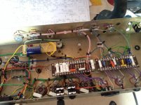
I've attached the schematic and a photo of the amp guts. The preamp was based on a design found here:http://www.chambonino.com/construct/constwire1.html which may be familiar to some. Below are links to a couple of video's demonstrating the problem, and another weird issue as well.
https://www.dropbox.com/s/swvvxrt4ddxbqr5/2014-05-25%2015.23.46.mov
https://www.dropbox.com/s/x48nlm0e38lj95t/2014-05-25 15.24.45.mov
Attachments

Last edited:
If you remove R14,does that improve it? If it does the feedback is the wrong way around. What is your neg bias set at and what output valves are you using?
Removing R14 didn't make any difference as far as I could tell.
Output valves are EL34's with -46v bias voltage applied.
Output valves are EL34's with -46v bias voltage applied.
I am not that tube expert but I suspect the phase splitter does not work properly.
V4B works as a constand current source, so only the upper half of your power tubes get a signal.
Feedback path modulates common cathode of V4 instead of driving the grid of V4B.
This may explain your nasty "half wave" distortion.
V4B works as a constand current source, so only the upper half of your power tubes get a signal.
Feedback path modulates common cathode of V4 instead of driving the grid of V4B.
This may explain your nasty "half wave" distortion.
I would first check DC levels are OK.
Then check AC levels don't clip anywhere as they pass through the amp.
Then check AC levels don't clip anywhere as they pass through the amp.
I am not that tube expert but I suspect the phase splitter does not work properly.
V4B works as a constand current source, so only the upper half of your power tubes get a signal.
Feedback path modulates common cathode of V4 instead of driving the grid of V4B.
This may explain your nasty "half wave" distortion.
The PI circuit is pretty much industry standard, you'll find an identical design in just about every other guitar amp.
Errm, this is weird. But the problem seems to have gone away. I did re-solder a few joints but didn't notice any change right away. Now it seems fine. 😕
It might be worth including a grid stopper on V1b. This would help to prevent any ultrasonic instability due to parasitic coupling.
Did you check DC voltages as recommended? We could help you better if you repost schematic with voltage readings at tube plates, cathodes, and grids.
If DC voltages are fine use a scope to trace an input signal through the circuit.
If DC voltages are fine use a scope to trace an input signal through the circuit.
I am not that tube expert but I suspect the phase splitter does not work properly.
V4B works as a constand current source/QUOTE]
There's no constant current source anywhere in that circuit, the phase splitter is a standard long tailed pair.
'If' there was going to be a constant current source in it at all, it would be in the common cathodes of that long tailed pair, but it's not really something you do with valves.
It might be worth including a grid stopper on V1b. This would help to prevent any ultrasonic instability due to parasitic coupling.
I did add a 150k grid stopper when I was first trying to fix the issue but it didn't make any difference I could tell. Embarrassing as it is I get the feeling the problem was something as banal as a weak solder joint as the amp works fine now although it seems to have developed a little hum, but nothing major.
I have further mod plans for this, mainly adding a master volume before the PI so the existing volume pot becomes more of a "post gain" control so I can add the extra drive without having to blow the roof off.
I made a video of me improvising some doom riffs using a variable attenuator pedal I made a while ago to approximate clean/dirty switching.
https://www.youtube.com/watch?v=bIYfUcHm6QA
- Status
- Not open for further replies.
- Home
- Live Sound
- Instruments and Amps
- Seeking troubleshooting advice for my first amp build.