I recently purchased a power transformer which purportedly came from a British tube, er, valve guitar amplifier from the 1960s. I can find no documentation for it so I will need to test it to sort out the windings.
I understand it is not advisable to just plug it into the mains and probe the solder lugs so I’m cobbling together a much safer test setup.
Here’s what I have on hand:
1) Hammond 369AX power transformer. This was originally ordered for use with a tube phono preamp, hence the filament supply. Seeing as it’s 125-0-125V (40VA), I’m assuming I can use it as an isolation transformer.
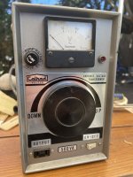
2) Older model Calrad 45-739 variac. I can’t find a manual for it but it looks good and feels good under adjustment. It’s fused (5A) and rated at 500VA. I don’t have the three prong adapter as seen in the picture but have one around somewhere I can use as seen in the link.
I’m going to set the variac at 1/10 the mains voltage.
The testing arrangement will be mains —> isolation transformer primary::secondary —> variac —> DUT
so anyway, am I good to go? Any suggestions? Should I fuse the isolation transformer as well?
thanks in advance.
I understand it is not advisable to just plug it into the mains and probe the solder lugs so I’m cobbling together a much safer test setup.
Here’s what I have on hand:
1) Hammond 369AX power transformer. This was originally ordered for use with a tube phono preamp, hence the filament supply. Seeing as it’s 125-0-125V (40VA), I’m assuming I can use it as an isolation transformer.
2) Older model Calrad 45-739 variac. I can’t find a manual for it but it looks good and feels good under adjustment. It’s fused (5A) and rated at 500VA. I don’t have the three prong adapter as seen in the picture but have one around somewhere I can use as seen in the link.
I’m going to set the variac at 1/10 the mains voltage.
The testing arrangement will be mains —> isolation transformer primary::secondary —> variac —> DUT
so anyway, am I good to go? Any suggestions? Should I fuse the isolation transformer as well?
thanks in advance.
Attachments
If you care about getting each winding's phase polarity correct (signified by a "dot" on one end of the coil symbol on the schematic), there's an old thread that might possibly help:
A little tester to determine transformer PhaseDots with no scope or signal generator
A little tester to determine transformer PhaseDots with no scope or signal generator

Too complicated. I'd use a healthy 6.3V heater transformer (isolation) and a 10 Ohm 10 Watt series resistor (anti-smoke). First try to feed the 6V into a presumed 120V or 240V winding. If you get that right, on a tube PT you will find another winding at 0.3V or 0.15V, the original 6V winding ratio-ed by 120:6 or 240:6. (A 0.25V winding is obviously a 5V winding.) Now your high voltage winding will be dozens-Volt at most, not hundreds.
When you are real sure you know which winding is witch, the same 6.3VAC+10r rig into the 6.3V winding of the mystery iron will give nearly original voltages (including the deadly ones!) with no risk of fire and little risk to you if you use your head and do not try to hold probes on leads.
When you are real sure you know which winding is witch, the same 6.3VAC+10r rig into the 6.3V winding of the mystery iron will give nearly original voltages (including the deadly ones!) with no risk of fire and little risk to you if you use your head and do not try to hold probes on leads.
Actually, any small wall wart that gives AC should work...there is no need for a heater transformer, specifically. Though 6.3 may give more accurate readings.
And due to metal hysteresis, you may get approximate readings, which is okay, you need to identify the windings.
Take care, this is high voltage stuff. Lethal.
And due to metal hysteresis, you may get approximate readings, which is okay, you need to identify the windings.
Take care, this is high voltage stuff. Lethal.
If it was me, I'd simply Variac right to the AC input windings - as long as you have one on hand - the transformer under test will provide AC line isolation to the secondaries. Rotate the control to zero before turning power on. Bring it up to the 10-12 volt range; best to measure with your DMM, vs the variac's meter. Your secondaries should be about 1/10 of what you'd see plugged straight into the wall.
Too bad that particular variac doesnt have a current meter as well. I cant imagine the transformer presenting a high current situation at 11V in, unless it was shipped to you with all the secondary tabs shorted. Which is ridiculous. Be careful and good luck.
Too bad that particular variac doesnt have a current meter as well. I cant imagine the transformer presenting a high current situation at 11V in, unless it was shipped to you with all the secondary tabs shorted. Which is ridiculous. Be careful and good luck.
First thing I did was continuity test the windings. I’m going to start a thread on the topic of the transformer itself.
Here’s a preview of it:

Selmer T205A power transformer
7-6: 0.2 ohms
1-12: 5.0 ohms
1-11: 5.0 ohms
3-5: 67.6 ohms
3-4: 31.4 ohms
4-5: 40.1 ohms
2-X: OL
8-9: 0.1 ohms
8-10: 0.1 ohms
9-10: 0.1 ohms
(Guesses: 3-4-5 is secondary; 6-7 is 5V; 8-9-10 is 6.3v)
Here’s a preview of it:
Selmer T205A power transformer
7-6: 0.2 ohms
1-12: 5.0 ohms
1-11: 5.0 ohms
3-5: 67.6 ohms
3-4: 31.4 ohms
4-5: 40.1 ohms
2-X: OL
8-9: 0.1 ohms
8-10: 0.1 ohms
9-10: 0.1 ohms
(Guesses: 3-4-5 is secondary; 6-7 is 5V; 8-9-10 is 6.3v)
Okay. The local hardware store’s electrical aisle was pretty bleak and all I could find towards this setup was some insulated alligator clips and a two prong power cord. Looks like I’m going to just plug the variac directly into the mains. I’ll make sure all connections are made and the variac is set to 0V before power up. My DMM negative probe is a clip so I can keep one hand in the pocket.
The existing fuse on my variac is the input I’m assuming. You’re suggesting I put another fuse in series with the negative voltage between the variac and the transformer primary?
Could, if you verify for certain that the cord fuse is in the hot (black) lead,
and that this fused hot lead goes to the Variac input terminal when plugged in.
And also verify that the Variac is properly wired. And your wall outlet.
Does everything have 3 pin IEC plugs and sockets?
and that this fused hot lead goes to the Variac input terminal when plugged in.
And also verify that the Variac is properly wired. And your wall outlet.
Does everything have 3 pin IEC plugs and sockets?
No, the variac power cord is two prong as is the power cord I purchased for clipping to the power transformer for testing.
I can almost guarantee you nothing is wired properly at the place I rent. Nothing is, not an exaggeration.
sounds like I need to go to a Starbucks and use one of their outlets, lol.
sounds like I need to go to a Starbucks and use one of their outlets, lol.
Maybe at a friend's house. Don't assume anything, this is kinda dangerous.
Instead, if you have a signal generator, just set it to 60Hz and run its max output into the DUT transformer
primary directly. No Variac needed. Measure the input and output ACV with DVMs.
But still use the same caution as if it were 120VAC.
Instead, if you have a signal generator, just set it to 60Hz and run its max output into the DUT transformer
primary directly. No Variac needed. Measure the input and output ACV with DVMs.
But still use the same caution as if it were 120VAC.
- Home
- Design & Build
- Equipment & Tools
- Seeking input regarding a power transformer testing setup