Hi friends,
I am hoping to get some other eyes on a design I am working on. This is only my second and I am new, had help with the first from a gracious DIYer, trying to put the knowledge gained to work on my next one, any input is appreciated. I apologize in advance for the book-long post, I make no assumption that I should/will receive any assistance, but if you read on and are willing to give your input, you are a saint.
In general, it is a 6J5 input, 45 output parafeed headphone amplifier. Both stages will be cascode CCS loaded, planned output transformers are Sowter 8665. Mains transformer will be custom-wound by Sowter as well, targeting 300VAC HT secondary right now. DHT filament regulators will be Rod Coleman, including his raw DC supplies (not shown in the schematic)
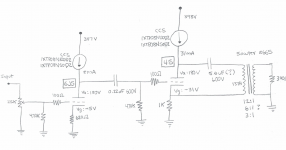
Here is my draft of the amplifier schematic:
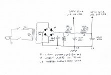
Draft of the HT power supply schematic:
Notes on the amplifier schematic:
Notes on the power supply schematic:
Here is where I am having some trouble...choosing a load line/OPT turns ratio. The Sowter 8665 has a 137H primary inductance, a 10K primary with the ability to wind for three different secondaries, 12:1 (65ohm), 6:1 (260ohm), 3:1 (600). I use 300ohm headphones, primarily.
Sowter 8665: SOWTER TYPE 8665
Given this is a headphone amplifier, and the power supply is already quite inefficient given the CCS output load, I am opting for a 180V 31mA bias point for the 45.
The way I am coneptualizing these load lines - the "infinite" AC impedance of the CCS on the ouput is in parallel with the OPT primary, such that the full load seen by the tube is essentially the primary impedance, for calculation purposes.
When it comes to the peak-to-peak voltage swing at my 180V 31mA bias point, the positive grid swing will be limited by the 0V grid curve, and the negative swing will be limited by the B+ at the top of the CCS (minus some headroom for the CCS drop out voltage, ~10V). As such, the 0V grid curve is the first of these two limitations and dictates the peak-peak swing.
With all of that being said, a 300ohm secondary will give the following impedance ratios with the three different turns ratios:
The load lines for these three windings, my 45 bias point, and 300ohm secondary are below. Here is an example of how I came up with them, with the 12:1 winding ratio:
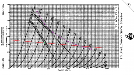
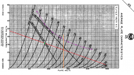
Assuming all of that is accurate, which may be a HUGE assumption 🙂 here are the load lines in red, bias point in green, peak negative swing in orange, max anode dissipation in purple:
12:1 winding ratio, 180V, 31mA, 46.2K
6:1 winding ratio, 180V, 31mA, 11.5K
3:1 winding ratio, 180V, 31ma, 5K
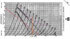
There is some concern on the 12:1 46.2K load line, as it passes above the max anode dissipation on the negative peaks, however, given the tube will clip at 0V grid much earlier than this (not to mention I would be deaf), is this truly a concern?
The crux of my problem is which winding I should be using for a 300ohm load, and if there is anything else I am overlooking (quite likely).
The OTHER major question, which I believe will need to be answered via experimentation, is the size of the parafeed cap. I understand there are ways to estimate its value using choke load, but for CCS, I don't believe there is. I came across a post by Paul Joppa of Bottlehead stating that there is no reliable way to calculate the parafeed capacitor size for a CCS load, but to try various sizes and take frequency response measurements.
If you have gotten this far, thank you!!! I hope this is not a tall ask to have someone else look over my work, but I am a firm believer in learn-by-doing, some of this information is not easy to come buy, been at it for three months non-stop, and I am no engineer :/
Thanks again.
I am hoping to get some other eyes on a design I am working on. This is only my second and I am new, had help with the first from a gracious DIYer, trying to put the knowledge gained to work on my next one, any input is appreciated. I apologize in advance for the book-long post, I make no assumption that I should/will receive any assistance, but if you read on and are willing to give your input, you are a saint.
In general, it is a 6J5 input, 45 output parafeed headphone amplifier. Both stages will be cascode CCS loaded, planned output transformers are Sowter 8665. Mains transformer will be custom-wound by Sowter as well, targeting 300VAC HT secondary right now. DHT filament regulators will be Rod Coleman, including his raw DC supplies (not shown in the schematic)
Here is my draft of the amplifier schematic:

Draft of the HT power supply schematic:

Notes on the amplifier schematic:
Plan to leave the 6J5 cathode resistor unbypassed, modest loss of gain on my LTSpice model with the CCS load in parallel with the 470K grid leak
Leaving the 45 cathode resistor unbypassed as well with the OPT grounded at the top of the cathode resistor, an "ultrafeed" configuration. My understanding is the opposite phase AC signal here will cancel and prevent cathode degeneration. LTSpice model seems to agree here too
Cascode CCS are the IXTP08N100D2 top device and IXTP08N50D2 bottom device offered by K&K audio. The 6J5 CCS will use the included 3W heat sink. As of right now, I am hoping to mount the 45 CCS to the aluminum chassis (K&K has a kit for this express purpose), it will need to dissipate ~6W
Notes on the power supply schematic:
Plan to use 600V Nichicon electrolytics for C1, C2, C3: https://www.mouser.com/datasheet/2/293/e-lgn-1511829.pdf
Lundahl chokes are likely overkill, I understand parafeed has very high PSRR, unsure how much filtering is necessary given the OPT will have a low turns ratio since this is a headphone amp
Diodes are fast-switching, soft recovery types from Vishay, VS-HFA06TB120-M3
I plan to add some sort of inrush current limiting, perhaps NTC thermistor, TBD
According to PSUD2 model, this supply yields 10mV peak-peak ripple at the top of the 45 CCS, 2uV peak-peak ripple at the top of the 6J5 CCS
Here is where I am having some trouble...choosing a load line/OPT turns ratio. The Sowter 8665 has a 137H primary inductance, a 10K primary with the ability to wind for three different secondaries, 12:1 (65ohm), 6:1 (260ohm), 3:1 (600). I use 300ohm headphones, primarily.
Sowter 8665: SOWTER TYPE 8665
Given this is a headphone amplifier, and the power supply is already quite inefficient given the CCS output load, I am opting for a 180V 31mA bias point for the 45.
The way I am coneptualizing these load lines - the "infinite" AC impedance of the CCS on the ouput is in parallel with the OPT primary, such that the full load seen by the tube is essentially the primary impedance, for calculation purposes.
When it comes to the peak-to-peak voltage swing at my 180V 31mA bias point, the positive grid swing will be limited by the 0V grid curve, and the negative swing will be limited by the B+ at the top of the CCS (minus some headroom for the CCS drop out voltage, ~10V). As such, the 0V grid curve is the first of these two limitations and dictates the peak-peak swing.
With all of that being said, a 300ohm secondary will give the following impedance ratios with the three different turns ratios:
12:1 >>> 46.2K:300, ~16ohm output impedance with 45 ra = 1650, P into 300ohms = 150mW
6:1 >>> 11.5K:300, ~47ohm output impedance, P into 300ohms = 400mW
3:1 >>> 5K:300, ~103ohm output impedance, P into 300ohms = 757mW
6:1 >>> 11.5K:300, ~47ohm output impedance, P into 300ohms = 400mW
3:1 >>> 5K:300, ~103ohm output impedance, P into 300ohms = 757mW
The load lines for these three windings, my 45 bias point, and 300ohm secondary are below. Here is an example of how I came up with them, with the 12:1 winding ratio:
10K:65ohm = 154:1 impedance ratio = 42.6K:300ohm
V = 31mA x 46.2K = 1431V (to determine slope of the load line)
Output impedance = (1650ohm ra of 45 / 154) + 4ohm DCR secondary resistance of Sowter 8665 = 16ohm
Peak-peak voltage swing = 226V, 226V/(2sqrt(2)) = 80Vrms, (80*80Vrms)/42.6K = 150mW
V = 31mA x 46.2K = 1431V (to determine slope of the load line)
Output impedance = (1650ohm ra of 45 / 154) + 4ohm DCR secondary resistance of Sowter 8665 = 16ohm
Peak-peak voltage swing = 226V, 226V/(2sqrt(2)) = 80Vrms, (80*80Vrms)/42.6K = 150mW
Assuming all of that is accurate, which may be a HUGE assumption 🙂 here are the load lines in red, bias point in green, peak negative swing in orange, max anode dissipation in purple:
12:1 winding ratio, 180V, 31mA, 46.2K

6:1 winding ratio, 180V, 31mA, 11.5K

3:1 winding ratio, 180V, 31ma, 5K

There is some concern on the 12:1 46.2K load line, as it passes above the max anode dissipation on the negative peaks, however, given the tube will clip at 0V grid much earlier than this (not to mention I would be deaf), is this truly a concern?
The crux of my problem is which winding I should be using for a 300ohm load, and if there is anything else I am overlooking (quite likely).
The OTHER major question, which I believe will need to be answered via experimentation, is the size of the parafeed cap. I understand there are ways to estimate its value using choke load, but for CCS, I don't believe there is. I came across a post by Paul Joppa of Bottlehead stating that there is no reliable way to calculate the parafeed capacitor size for a CCS load, but to try various sizes and take frequency response measurements.
If you have gotten this far, thank you!!! I hope this is not a tall ask to have someone else look over my work, but I am a firm believer in learn-by-doing, some of this information is not easy to come buy, been at it for three months non-stop, and I am no engineer :/
Thanks again.
Last edited:
6W is way too much to dump into a chassis plate. You will need a very large heatsink and maybe forced air cooling for that.
You want a 5K:8 transformer, maybe a 5K:8/16. A #45 has enough self noise that lower step-down ratios aren't going to be particularly quiet.
5.6uF is a perfectly reasonable starting point for the parallel feed cap.
You want a 5K:8 transformer, maybe a 5K:8/16. A #45 has enough self noise that lower step-down ratios aren't going to be particularly quiet.
5.6uF is a perfectly reasonable starting point for the parallel feed cap.
Thanks audiowize. The suggestion was made to me to swap the top CCS device, the IXYS IXTP08N100D2 for a United SiC JFET for ease of cooling, I haven't taken a dive into that yet.
As far a 5K:8/16 transformers go, my first draft of this project used the Sowter 8983, which is a parafeed transformer that fits that description. Taking this approach, you would parallel an ~8/16ohm resistor with the 300ohm headphone output to give the 45 its 5K load?
As far a 5K:8/16 transformers go, my first draft of this project used the Sowter 8983, which is a parafeed transformer that fits that description. Taking this approach, you would parallel an ~8/16ohm resistor with the 300ohm headphone output to give the 45 its 5K load?
1. If the current source has the same standing current, and the same voltage across it,
then it will dissipate exactly the same wattage, and will dump exactly the same heat into the chassis.
2. Consider an output transformer:
The primary has a specific inductance, and so a specific inductive reactance versus frequency.
This inductive reactance is in parallel with 2 things:
A. The 45's plate resistance, rp;
B. The reflected impedance at the primary from the load on the secondary.
With the high inductive reactance caused by 137 Henry, the 45 plate resistance, rp, will be much lower than that, so it is not an issue at low frequencies even with a high impedance load on the secondary.
C. The distributed capacitance of the primary might cause the high frequencies to roll off, if the capacitive reactance is not higher than the 45's rp.
But if the secondary is loaded with a low enough impedance, that reflection back to the primary will nicely swamp out the primary's capacitive reactance.
A simple test of the high frequency response with the headphones connected will indicate whether the primary capacitance is an issue with the secondary not loaded heavily enough.
Happy listening!
Last edited:
I suppose without the paralleled resistor, I would be looking at flat load line.
For 5K:8, 25:1 turns ratio, ~30mW into 300ohms
For 5K:16, 17:1 turns ratio, ~60mW into 300ohms
I'll reconsider it.
For 5K:8, 25:1 turns ratio, ~30mW into 300ohms
For 5K:16, 17:1 turns ratio, ~60mW into 300ohms
I'll reconsider it.
Thanks 6A3, I did look at the influence of inductive reactance on frequency repsponse after my original post, taking into account the anode and reflected primary impedance, and came to the same conclusion, the low frequency response doesn't appear to be an issue. I would expect the same for the Sowter 8983 if the change is made.
The capacitive reactance of the primary, however, I had not considered. I'll do some reading into it, thanks for bringing it up.
I'll have to think of a better cooling solution for the 45 CCS, in addition to possibly changing the primary device.
The capacitive reactance of the primary, however, I had not considered. I'll do some reading into it, thanks for bringing it up.
I'll have to think of a better cooling solution for the 45 CCS, in addition to possibly changing the primary device.
Last edited:
Hmm, that's an idea. I have a pair of NOS Mullard XF2 EL34 burning a hole in my pocket, think those would work?
.
.
.
.
.
Just kidding 🙂 I will look into it, might add more complexity than I'd like and increase the footprint of the amp, trying to keep it somewhat compact (right now looking at a 9.5"x12" layout), but it is a good idea to consider, will have to weigh that against better cooling for the FET.
.
.
.
.
.
Just kidding 🙂 I will look into it, might add more complexity than I'd like and increase the footprint of the amp, trying to keep it somewhat compact (right now looking at a 9.5"x12" layout), but it is a good idea to consider, will have to weigh that against better cooling for the FET.
Sure, an EL34 could be used as a plate load. I think Pete Millett did that at some point.
A #45 doesn't need a ton of current, so a 6AQ5 would be OK as a load too.
A #45 doesn't need a ton of current, so a 6AQ5 would be OK as a load too.
Some current sources have more burden voltage than others.
One that needs at least 70V to work, will require more B+ than one that only needs 10V to work.
Tube current sources often have more burden voltage than solid state current sources.
Some of the lowest burden voltage devices are good chokes. Current x DCR.
Some of Doc Bottlehead's product line's claims to fame used chokes in the 45, 2A3, 300B, and other tube output stages.
All designs have tradeoffs.
Last edited:
Understood. I would like to avoid increasingly the B+ further, that will have a cascading effect. Most likely I will pursue a way to sink 6W from the 45 CCS, perhaps a pair of large heat sinks bolted to the chassis would suffice? Or maybe I can mount the device directly onto a the heat sink through a drilled hole with the heat sink external to the chassis...the panel is 4.25" x 9.5" of an anodized aluminum 0.125" thick. I think one of these two solutions will work. Otherwise, I might need to revisit using an anode choke.
Last edited:
Perhaps have some thought towards skipping an output transformer cost and use some cheap power tubes: Philips type OTL amp for 600 Ohm headphones
(there are some good links in that htread).
Only item to watch is the maximum filament - cathode voltage, you might like seperate 6.3V windings.
If you want to step down to 4 / 8 ohm then you can use a standard toroid (mains) transformer....
And if you have some EL34 PP OPT then you can squeeze 30 - 40 watts out of a pair in PP.
Last edited:
You don't want the heat sink for the CCS MOSFET to be grounded to the chassis. You have enough loss of AC impedance from the internal devise capacitance without creating a capacitor from the Drain of the top MOSFET to chassis ground.
Perhaps have some thought towards skipping an output transformer cost and use some cheap power tubes: Philips type OTL amp for 600 Ohm headphones
(there are some good links in that htread).
Only item to watch is the maximum filament - cathode voltage, you might like seperate 6.3V windings.
If you want to step down to 4 / 8 ohm then you can use a standard toroid (mains) transformer....
And if you have some EL34 PP OPT then you can squeeze 30 - 40 watts out of a pair in PP.
Thanks for the link, at a glance looks like an interesting amplifier. I'm quite committed to the build I posted (or a similar variation), but I will save the thread for future reference. And yes, an EL34 class A PP build is in my future, but I am trying to do a few single-ended builds first.
You don't want the heat sink for the CCS MOSFET to be grounded to the chassis. You have enough loss of AC impedance from the internal devise capacitance without creating a capacitor from the Drain of the top MOSFET to chassis ground.
Of course! I will not ground the FET to the chassis, it will be isolated no matter the solution. I may look into a large PCB mount TO-220 heat sink for the device and modify my chassis for better ventilation, Ohmite has some that may do the trick.
FA-T220-64E - Ohmite Mfg Co
Of course! I will not ground the FET to the chassis,
That's not what I said. Even with a thermal pad and shoulder washers to isolate FET from the heat sink it will still form a capacitor from the top Drain to ground if the heat sink is grounded. The whole point of a CCS load is hight AC impedance. More capacitance will kill some of that at high frequencies. Keep the heat sink isolated and don't use grounded chassis for a heat sink.
I will more likely use a PCB mounted heat sink mentioned in my last post with better chassis ventilation, so it should not be a concern. If a chassis mount heat sink is used, I'll be sure it is isolated from ground. Thanks for raising the concern 🙂
I would also suggest that you should plan on trying your circuit with bypass caps on the #45 bias resistors.
Sure thing, should be easy enough to clip in some bypass caps, give it a listen and take some measurements, see which connection is preferred, thanks for the idea.
By the way, I came across another DIYer who had the same experience with the 45 regarding noise and a high-turns-ratio OPT, so all but certain I will use the Sowter 8983 (5K:8/16) instead. Great tip.
By the way, I came across another DIYer who had the same experience with the 45 regarding noise and a high-turns-ratio OPT, so all but certain I will use the Sowter 8983 (5K:8/16) instead. Great tip.
Last edited:
That's not what I said. Even with a thermal pad and shoulder washers to isolate FET from the heat sink it will still form a capacitor from the top Drain to ground if the heat sink is grounded. The whole point of a CCS load is hight AC impedance. More capacitance will kill some of that at high frequencies. Keep the heat sink isolated and don't use grounded chassis for a heat sink.
I just measured the capacitance between an IXCP10M45, mounted to an aluminum heatsink, insulated with a standard sil-pad. Capacitance between the device and heatsink was about 40pF.
40pF is an impedance of 199k at 20kHz. The Rp of a 45 is about 4k.
So, can you explain why it is a problem mounting the CCS to a grounded heatsink on a 45?
Pete
- Home
- Amplifiers
- Tubes / Valves
- Seeking Guidance - 45 Parafeed Headphone Amp Design