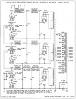
I don't get what the diodes do, especially the one between the 300B's plate and the OT. Just to be different?
Best regards!
Best regards!
The voltage drop across the plate chokes of input and driver tube sets bias. The diode between opt and 300B anode might be a version of a japanese circuit that uses a silicon diode between B+ and opt (I keep forgetting the name of it, it was discussed at length at the JoeList and everywhere else at some point).
At some point I was influenced by the writing on the chimeralabs website while designing a power amp. I did copy the thing with the 1uF capacitor input for the B+ supply. It gave the worst of both L and C and after changing to L input filters and adjusting voltage was much happier with the amplifier...
Remembered the mentioned amp: http://www2u.biglobe.ne.jp/~hu_amp/amput3e.htm
Again about the Chimera Labs circuit: personally I like the stacked supply dc coupling, I also use that topology in my power amps. That Axiom circuit is difficult to get right as it has no way to adjust bias of the 300B and 6Y6. Adding a potentiometer befor the plate chokes of the 6Y6 and the 6J5 helps in that regard.
A potentiometer defeats the whole idea of a resistor-less amplifier with "no capacitors in signal path". 😀
See Hoekstra DC-Coupled 300B ... oooooh!I don't get what the diodes do, especially the one between the 300B's plate and the OT. Just to be different?
LOL 😀
Especially "Constant current" 😀
If to replace diodes by resistors, resistors have to be shunted by caps. or better to use Zeners for that purpose. The lower stage gets bias from a diode, while upper 2 get bias from DCR of chokes, so I would eliminate all upper diodes, using IR LED to bias the lower tube.
Edit: I would never rely on such multi-floor bias supply for the upper tube. Probably, the major role of diodes is, to reduce stress on the upper tube upon powering on the amp.
Last edited:
Yes, Wavebourn has pointed out that he would not do it that way. But for anybody that does, there needs to be some very close control of the voltage drop across the choke load of the 2nd stage.
There are some other often noticed factors that act a little like 'self bias'. A major factor of that amplifier topology that does ‘set the bias’ is the 1uF input capacitor.
I will ‘change’ the amp parts (theoretically) to illustrate that major factor. (one factor at a time, then the other 2 major factors after that). Replace the tube rectifier with low voltage drop solid state diodes. Replace the power transformer with one that has 0 Ohms DCR primary, and 0 Ohms DCR secondary.
The 300B HV comes from a 425VAC secondary. 425VAC = 601V peak. Do not worry, we would not actually use this high of a B+ voltage, this is just an illustration.
Start with tube #1, a 300B that tries to draw 90mA. 1 uF has 1326 Ohms of capacitive reactance at 120Hz. 90mA x 1326 Ohms = 119V peak to peak ripple across the 1uF cap. 119V/2 = 59.5V average 601V - 59.5V = 541.5V B+ at the 1uF filter cap.
Start with tube #2 a 300B that tries to draw 70mA. 1 uF has 1326 Ohms of capacitive reactance at 120Hz. 70mA x 1326 Ohms = 92.8V peak to peak ripple across the 1uF cap. 92.8V/2 = 46.4V average 601V - 46.4V = 554.6V B+ at the 1uF filter cap.
Of course, the actual B+ will be lower, you have the drop in the DCR of the choke. But this is a discussion to show a main factor of where the B+ settles. If Tube #1 draws 90mA, then the B+ drags Down to 541.5V. If Tube #2 draws only 70mA, then the B+ lets the B+ go Up to 554.6V. The difference in the B+ is 554.6 versus 541.5V. 554.6V - 541.5V = 13.1 Volt difference. But the 300B plate resistance, rp, is about 700 Ohms. 13.1V/700 Ohms = 18.7 mA.
So the tube trying to draw 90mA will now try to draw ~ 90 - 18.7 = 71.3mA. So the tube trying to draw 70mA will now try to draw ~ 70 + 18.7 = 88.7mA. Now the 1uF capacitor will cause the B+ to be lower with tubes that try to draw higher current, and B+ will be higher with tubes that try to draw lower current. As you can see, this is somewhat self adjusting the different 300B tubes to draw similarly close currents.
Then, we also have the same effect when we use a real transformer that does have DCR in the primary and secondary windings. Larger current draw causes lower B+, smaller current draw causes higher B+, and so the current settles in the middle.
And there is the same effect when we use a rectifier tube. Higher current drops more voltage across the rectifier (lower B+), and lower current draws less voltage across the rectifier (higher B+)
These 3 factors tend to make all good 300B tubes draw similar current. Of course, self bias is even better at making the currents more equal.
The purpose of the 6CG3 and 6BE3 ‘Damper Diodes’ in this amplifier is that they have a very slow warm-up. So, they Soft Start the 3 amplifier tubes here. Right?
I am generally not a fan of most DC coupled circuits. You 'solve' one problem, and create one or more new problems. I know, there are many good implementations of DC coupled circuits, and probably as many that are not good at all.
Soft start is a nice feature using stacked supplies. I use a 80 direct heated rectifier tube with silicon diodes to ground to make a bridge rectifier for the input stage and an 83 with 6AX4s towards ground in the stacked stage.
The input comes up fast pulling the grid of the stacked stage negative (sorry, english not my first language...) before the B+ of the stacked stage comes up slowly. It isn't cheap or effective or any of that stuff, but HEY! it works and is fun...
The input comes up fast pulling the grid of the stacked stage negative (sorry, english not my first language...) before the B+ of the stacked stage comes up slowly. It isn't cheap or effective or any of that stuff, but HEY! it works and is fun...
- Status
- Not open for further replies.
- Home
- Amplifiers
- Tubes / Valves
- Seeking feedback! Anyone has built Chimera Labs Axiom??