I etched my first PCB last night - what a blast! It was a Borbely preamp to compare to my UGS under construction.
Moving to the F5 - I'm playing around with different configurations (XF5, cascoding, different outputs) and having a PCB pattern to help makes sense. I failed at a point to point F5 attempt and now see the benefit of PCBs. I dug through the threads and found a couple of PCB layouts. I'm hoping to see what a few others have done and piggyback on their work.
If you have an interesting single sided F5 layout, would you consider posting?
Thanks
PS. it may not be interesting but I hope it helps.
PM if you need DXF or PCB files.
What do you use to get from paper to copper?
Al
PM if you need DXF or PCB files.
What do you use to get from paper to copper?
Al
I am very value oriented. This trait delays projects, but it ensures I don't waste money.
As such, I used the magazine method. I got a VERY usable board with my first try. Now that I see how it works, I have very high confidence I can make good boards easily. My next challenge is double sided boards.
I'll try those over the weekend.
As such, I used the magazine method. I got a VERY usable board with my first try. Now that I see how it works, I have very high confidence I can make good boards easily. My next challenge is double sided boards.
I'll try those over the weekend.
PS. it may not be interesting but I hope it helps.
PM if you need DXF or PCB files.
What do you use to get from paper to copper?
Al
http://www.diyaudio.com/forums/attachment.php?attachmentid=200247&stc=1&d=1291945694
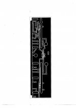
This is my F5 board.
It has two places for FET source resistors.
Board size is 110x70mm.
FET mounting hole distance with this board will be 140-145mm.
This is my F5 board.
It has two places for FET source resistors.
Board size is 110x70mm.
FET mounting hole distance with this board will be 140-145mm.
Attachments
Last edited:
XF5
I've been playing around trying to make an XF5 with IRF outputs. This is quite a feat for me as I have no training in either electronics or audio. As My first post in the current XF5 thread I proposed a mirrored Pass F5. I did not get any real input as to the viability of the idea.
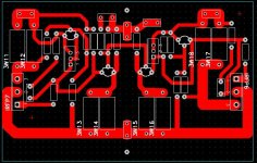
Now, Juma posted a nice F5 PCB layout, and I was able to paint in the parts to make the circuit I initially proposed. I don't really understand how to optimize the circuit for 8 ohm speakers, if anyone has thoughts, I'd appreciate them. Below is the PCB layout without the components. It was taken from Juma's design, so you can fill in the components with pen on paper if you're inclined.
Please let me know if you have any improvements.
I've been playing around trying to make an XF5 with IRF outputs. This is quite a feat for me as I have no training in either electronics or audio. As My first post in the current XF5 thread I proposed a mirrored Pass F5. I did not get any real input as to the viability of the idea.
Now, Juma posted a nice F5 PCB layout, and I was able to paint in the parts to make the circuit I initially proposed. I don't really understand how to optimize the circuit for 8 ohm speakers, if anyone has thoughts, I'd appreciate them. Below is the PCB layout without the components. It was taken from Juma's design, so you can fill in the components with pen on paper if you're inclined.
Please let me know if you have any improvements.
Attachments
Here it is:Juma,
It looks great. Would you happen to have a version with just the copper traces?

- Status
- Not open for further replies.
- Home
- Amplifiers
- Pass Labs
- Seeking F5 Single-sided PCB layout