When I was in college in the 1980's, I built a SWEET sounding amplifier kit by Mark V electronics called the TA-1000. It was supposed to be in class A operation for low level and moved to class B at high power... It was touted as a 100 watt unit into 8 ohms with exceptional noise and distortion performance. I had unlimited access to as many caps as I wanted, so I stuffed in 120,000uF caps on each power supply rail. I brought it to a high-end audio store in the day and sounded as good as ANY high end amp on the demo shelf. I recently pulled it out again and it sounds as good as I remember.
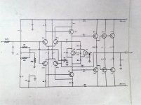
Sorry, but I do not have immediate access to the part values. I can get them, but it will be many months till I get back to the place where I left them. If I recall correctly, the output transistors Q9,10,11 and 12 are 2n3055(?) and MJ2955 (?). Q7 and Q8 are the TIP 41c and TIP 42c.
I dug up a schematic of the unit and wondered what made it sound so good. Perhaps I can get some comments from the group on its design, layout and whether it was anything fancy or just plain-Jane average. Let me know what I have here.
Attachments
Last edited:
there are 2 non-standard topology areas.
- the diff pairs feeding into the base and emitter of the VAS transistor.
- Q6 that seems to zero the bias setting only for positive voltage excursions
there are no short circuit protections.
- the diff pairs feeding into the base and emitter of the VAS transistor.
- Q6 that seems to zero the bias setting only for positive voltage excursions
there are no short circuit protections.
Actually there is only one non standard topology - just the Q6 “bias reduction” transistor. All high-ish-biased class B/AB amps will operate class A at lower levels, and revert to class B at sufficiently high levels - even without this feature. But it requires load current (due to the voltage drop in the emitter resistors) to do so. The only reason it is used is to force the bias to drop as the output voltage increases - even without a load. Why was this done? Because 2N3055’s really aren’t rated at a high enough voltage to be safe here. You need at least 80 volt (2x 40Vj rails to even approach 100W music power even if the supply were regulated. If an ordinary amp were biased high and run without a load, you would blow them - or at least be playing with fire. If more modern or at least 140V rated outputs (and drivers) were used, you could simply dispense with Q6 and its associated components.
The other feature - returning the collector of Q1a to the emitter of Q3 instead of the rail - is standard. It offers a slight boost in open loop gain. Not as much as using a current mirror, but that’s not straightforward to do with the dual diff pair approach. Perfectly valid, been done before.
What you would never never want to do is connect the wiper of the vbe pot directly to the base as shown. It makes what they are doing with Q6 easier, but if it gets intermittent or noisy, the bias will shoot for the moon and blow the amp. You should connect the wiper of the pot such that the bias *reduces* in such a fault condition.
So why did it sound (subjectively) as good as high end amps it was being compared to? There may not have been anything special about those particular amps either. You may be surprised to see how little there is in many of them. The amp referred to in the above post is a refined version of yours - topologically the same, but with definite refinements. Some peoples ears might not be “golden” enough to tell the difference. Two thing that did work in your favor - the 120,000 uF of overkill capacitance probably did help, especially if your transformer was small and you barely had enough rail voltage to start with. And lack of short circuit protection that almost always compromises the amp in some way. Just don’t short the speaker wires. Especially of no one is home to put out the fire.
Thank you for your kind and thoughtful responses folks!
I understand and assume the risk about the amplifier not having any output short protection. Everything I have is banana plug connectors and pose a really small chance of shorting.
Also, I believe that wg_ski hit the exact reason why my amp started on fire...most likely the pot around the Q6 got dirty and *poof*... Apparently, the all the caps in the power supply were still good, as were *most* of the components forward of the output stage, but every output transistor and power resistor got fried along with the PC board.
Fast forward to today... I rebuilt the bad channel and put a SEALED power potentiometer (2 watt) in the place of the old OPEN FRAME pot used on the original kit. I got 15 years out of it the first time, maybe I'll get 25 out of it this go around. Still sounds better than any solid state amp I have ever owned.
Clamp VR2 wiper to bottom with a couple of diodes series. In fact disconnect the wiper and see what you get for Idle bias current (no sound) with 1,2, or 3 diodes series. If it is under 80 ma, you win. High but not rediculous. Then put the wiper back and readjust to 20 ma or whatever your desired idle bias current was.
indianajo, thanks for the hint.. I will try it while bringing it up slowly with a variac as to not cause another thermonuclear accident.

Save above posted comments, I do not consider this design as a breakthrough.
Auto-nulling with C8 and a nulling pot VR1 - hard work for the feedback loop.
And C7. Now that's a Don Quixote solution with the front stage as giant windmills. Why?
What are your references claiming this amp as sounding so sweet and good?
Auto-nulling with C8 and a nulling pot VR1 - hard work for the feedback loop.
And C7. Now that's a Don Quixote solution with the front stage as giant windmills. Why?
What are your references claiming this amp as sounding so sweet and good?
What are your references claiming this amp as sounding so sweet and good?
I reference myself. I have an internally calibrated "sweet meter" and I use it sparingly. It sounds just like the sound you put into it...until it clips...then it doesn't. <sarc>
Seriously, it is surprisingly good for a very cheap Chinese kit from the 1980's... I like it.
I reference myself. I have an internally calibrated "sweet meter" and I use it sparingly. It sounds just like the sound you put into it...until it clips...then it doesn't. <sarc>
Seriously, it is surprisingly good for a very cheap Chinese kit from the 1980's... I like it.
That was my first DIY amp back in 1987. Tung Yung Soundmaster, aka TA-1000. Mine has a single pair of 2n3773 and 2n6609 output transistors.
In my experience it had harsh sound. I made few modifications and it become relatively polite. I disconnected D1 (effectively disabling sliding bias), disconnected R3 and R4 (DC offset was pretty ok without adjustment), increased C7 to 47pF, bypassed C8 with a 1uF film cap, replaced VR2 with enclosed one and set the quiescent current to 60mA.
And of course, I'd added 22000uF to the existing 4700uF in the power supply
Last edited:
Anyone's preferences are granted by default, no discussion about that.
This 'sweet meter' sounds as a unique selling point - just make a useless box tagged so and sell it for money. Who knows you become rich!
C7 is a miller-cap compensation (through Q1a) in the most difficult way, trying to avoid high local impedances but adding extra phase shifts in the open loop of the amp. Would not be my design choise.
LTP current limitation? Not familiar with that term.
BTW, I can't understand why yours sounded harsh. Mine was as smooth as silk... Perhaps there was an improvement between the TA-1000 and the TA-1000A (which I have).
BTW, I can't understand why yours sounded harsh. Mine was as smooth as silk... Perhaps there was an improvement between the TA-1000 and the TA-1000A (which I have).
Last edited:
With classic Miller compesantion, max slew rate depends on how much current can Long Tail Pair (aka differential amplifier) source/sink and the value of Ccomp.
In arrangement like C7 here, slew depends on VAS current which is less critical.
In arrangement like C7 here, slew depends on VAS current which is less critical.


Funny how it calls it a "pure class A" amplifier...
By the way... did you know that the company is still producing audio equipment in Hong Kong? Right now they are only producing tube equipment and some other goodies. Looks like a pretty impressive range of amplifier products and they actually look very familiar to me. Possibly rebranded stuff sold here in the USA, but I am not certain. 膽機製造商-------SOUND MASTER I used translator.google.com (and my wife who speaks and reads Mandarin) to get it into English.
By the way... did you know that the company is still producing audio equipment in Hong Kong? Right now they are only producing tube equipment and some other goodies. Looks like a pretty impressive range of amplifier products and they actually look very familiar to me. Possibly rebranded stuff sold here in the USA, but I am not certain. 膽機製造商-------SOUND MASTER I used translator.google.com (and my wife who speaks and reads Mandarin) to get it into English.
Last edited:
- Home
- Amplifiers
- Solid State
- Seeking expert comments on this power amp topology