Hi again
I posted a few days ago to say hello and describe my project, a KT88 PP ultralinear amp, which also happens to be my first valve amp build.
Nothing like jumping into the deep end.
Since then I've been reading a lot to achieve a sufficient understanding of preamp circuits. I could easily have just picked a schematic off the internet and built that, but I wouldn't have learned anything by just assembling a jigsaw puzzle. So I've been doing a lot of reading, a lot of modelling in TubeCad, and checking over my calculations.
Finally I have a preamp circuit that I am reasonably happy with on paper. The topology is simple: 12AX7 initial gain stage using the grounded cathode topology, followed by a balanced load inverter using the other half of the 12AX7, followed by a 12AU7 grounded-cathode driver stage.
It's all described in my blog post on the subject - what I'd really appreciate is for someone in this helpful community to look over my shoulder and let me know whether this looks OK or whether I've made any mistakes that'll bite when I come to build it.
So thanks in advance for anyone who takes the time 😀
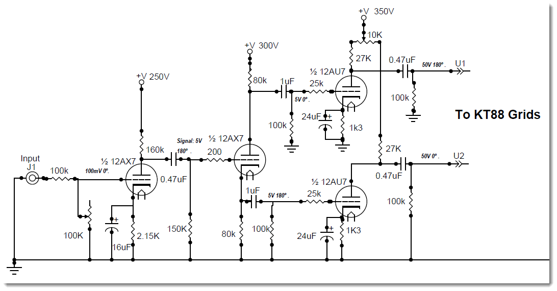
Suggested preamp stage
I posted a few days ago to say hello and describe my project, a KT88 PP ultralinear amp, which also happens to be my first valve amp build.
Nothing like jumping into the deep end.
Since then I've been reading a lot to achieve a sufficient understanding of preamp circuits. I could easily have just picked a schematic off the internet and built that, but I wouldn't have learned anything by just assembling a jigsaw puzzle. So I've been doing a lot of reading, a lot of modelling in TubeCad, and checking over my calculations.
Finally I have a preamp circuit that I am reasonably happy with on paper. The topology is simple: 12AX7 initial gain stage using the grounded cathode topology, followed by a balanced load inverter using the other half of the 12AX7, followed by a 12AU7 grounded-cathode driver stage.
It's all described in my blog post on the subject - what I'd really appreciate is for someone in this helpful community to look over my shoulder and let me know whether this looks OK or whether I've made any mistakes that'll bite when I come to build it.
So thanks in advance for anyone who takes the time 😀
Suggested preamp stage
Input stage will be unnecessarily noisy and has a best-case 6dB gain loss at the input. Second stage won't bias properly. Third stage misses opportunities for balance and will not have low distortion.
I'd strongly urge you to study the Williamson amp, which has the same basic topology, but done properly. There's a detailed analysis of it in the book "Valve Amplifiers" by Morgan Jones (4th edition), which is a book you should own and study carefully.
I'd strongly urge you to study the Williamson amp, which has the same basic topology, but done properly. There's a detailed analysis of it in the book "Valve Amplifiers" by Morgan Jones (4th edition), which is a book you should own and study carefully.
Input stage will be unnecessarily noisy and has a best-case 6dB gain loss at the input. Second stage won't bias properly. Third stage misses opportunities for balance and will not have low distortion.
Dire predictions indeed. Most of my reading comes from the tubecad journal
Let's confine to the input gain stage - can you point me in the direction of any errors? This is the basis for that circuit

Here's the bias point

From here: How to design valve guitar amplifiers
For your first stage, read Triode Gain Stage part. Yes, all of the pdf content.
For second stage, read the Cathodyne part.
For third stage, consider using the AC Long Tailed Pair design.
For your first stage, read Triode Gain Stage part. Yes, all of the pdf content.
For second stage, read the Cathodyne part.
For third stage, consider using the AC Long Tailed Pair design.
That is not a preamp. It is the voltage amplifier stages of a power amp. Learning a new subject involves learning the meanings of words.aros71 said:Finally I have a preamp circuit that I am reasonably happy with on paper.
The input stage will be noisy for two reasons:
1. it is preceded by an attenuator, whose maximum 'gain' is -6dB.
2. the attenuator uses high value resistances, so you get 50k-worth of thermal noise at maximum volume.
Why not use an ordinary volume control?
Were you intending to add negative feedback? If so, you need to be aware that achieving stability over four stages is difficult, which is why few people attempt it.
The lowish gain (approx half mu) of the first stage should alert you that it has too low an anode resistor, so increasing distortion. Fortunately, signal levels will be low so overall distortion may be acceptably low.
The LF rolloff at "2.58hz" looks wrong. 16uF in parallel with 2.15k gives 4.6Hz, but the cathode resistance (roughly 1/gm + Ra/mu) appears in parallel with Rk so something nearer 8-10Hz is more likely. If you look at other designs you will see that cathode bypass caps are usually more like 50uF.
Where did the 100mv. input sensitivity come from? Are you going to limit the source's output to that?
I'm a builder not so much a designer and all the good preamps I've see are one tube in a simple circuit like a 12b4 or 26....
Second stage won't bias properly. Third stage misses opportunities for balance and will not have low distortion...I'd strongly urge you to study the Williamson amp, which has the same basic topology, but done properly.
Aros71, do not despair. Folks here are trying to lead you down good avenues of investigation.
Here's a link to discussion of the Williamson amp that SY is referring to:
http://www.sowter.co.uk/pdf/Williamson Amplifier.pdf
Pay particular attention to the way that the driver stage is biased in the Williamson (shared cathode resistor).
Additionally, consider where the grid for the second stage gets its voltage reference and where that would be (in voltage terms) in relation to the cathode. You've got the right idea with the loading but the grid to cathode voltage difference (bias) is missing something important.
Last edited:
No problemo. I didn't know it was their either until I googled around a bit. Was just looking for the schematic (or a derivation) but found the jackpot.
Thanks for all the feedback (no pun intended!)
Useful feedback. As an academic the peer review process is always the harshest!
Specific responses to those who have contributed.
Sy
Configuration of volume control is an experiment. My main objective was not to have the carbon track of a potentiometer in the signal path, however this configuration may make more sense between the initial gain and the phase splitter, rather than directly at the input. In the circuit schematics I've studied so far I see about a 50/50 distribution in terms of where the volume control is positioned. This may be resolved by experimentation and/or increasing the pot to 1M instead of 100K.
Second (cathodyne) stage bias: Points well noted - it's sent me down a new rabbit hole of reading ... I'll post up a revision in a few hours with a voltage reference improvement.
3rd stage - 12AU7 Driver. I note that one resistors – and bypass capacitor – are frequently used. I could adjust my topology accordingly, would this make you happier? The bias point selected for the 12AU7 is on the blog pose I linked.
Williamson amp - I have read this and much of it is concerned with setting up the correct conditions to allow the negative feedback to be tied to the cathode of the initial gain stage without incurring feedback.
Ballpencil:
First, I'm not designing a guitar amp, though I understand a lot of the principles are the same. I understand that guitar amps almost universally use the long tail pair configuration for the phase splitter, whereas I am using a cathodyne (aka split-load). You're suggestion a second stage cathodyne and a third-stage long tail pair? Am I missing something or are you recommending two cascading phase splitters?
DF96:
Volume control/attenuator - refer my comment to Sy above - this may involve some experimentation to get it right.
Negative feedback - I will attempt it but I expect difficulties and may end up without!
Low gain: Is it desirable to use all of the valve's gain? Most 12AX7 initial gain circuits I've seen tend to run at around the same gain as mine… I was working loosely to the "Golden Ratio" proposed by Valvewizard in which suggests a Rp of approximately twice the plate resistance as a start point.
Regarding Ck - the values I am using are what TubeCad suggested, I'll research other designs to see if something like 47µF is more prevalent. What is the effect of too much capacitance?
20to20:
100mV was arbitrary - according to tubecad I can get up to 1.33v before encountering clipping on the input stage.
Sodacose:
RE bias of Cathodyne - see comment to Sy above who raised the same objection.
Finally, thanks very much to everyone who has taken the time to look this over for me. If we were in a bar the next round would be on me 😀
My main objective was not to have the carbon track of a potentiometer in the signal path...
But it is. Shunt is just as much "in the signal path" as series. Don't pull any current through it and you'll be fine.
I can thoroughly recommend reversing your design process. Start from the opt and work backward to the input.
Apropos the cathodyne vs ltp. The cathodyne and following gain stage in your design is a good way of using more tubes, but no better than a straight ltp - the nett voltage gain is the same either way (assuming design is done right). And one less stage is a heap better for complexity and stability.
A better topology (imo) would be voltage amp -> ltp ->cathode (or source) follower -> finals
Or go buck wild and split right up front with an input transformer, then you have gainblock options galore following that.
Even DTNW himself had trouble running feedback around so long a loop, so he did what he could to set a "dominant pole" at low frequencies, although the term wasn't in use yet (was it?). He direct coupled the first two stages, then used no cathode bypass capacitors, then used staggered RC time constants in the signal path, the first significantly larger than the second.
The second RC sets the amplifier's recovery time from overload, so is well placed to be the "dominant pole". Output transformer primary inductance must be large enough that, as it increases with signal level, its pole moves *away* from the dominant pole.
And he still had a subsonic lump. Many classic era commercial amplifiers were much worse.
High frequencies are hard to model, so it's cut and try. I'm glad to see the Audio Amateur pamphlet available on line - it's essential and hard to buy these days.
All good fortune,
Chris
20to20:
100mV was arbitrary - according to tubecad I can get up to 1.33v before encountering clipping on the input stage.
If 100mv gives you 50v of drive to the output tubes, what will 1v of input signal be by the time it gets to the output grids? If the gain is 50, which is what you have penciled in there, how can you go to 1.3v, and then 10x through the AU7's ?
If 100mv gives you 50v of drive to the output tubes, what will 1v of input signal be by the time it gets to the output grids? If the gain is 50, which is what you have penciled in there, how can you go to 1.3v, and then 10x through the AU7's ?
100mV at the grid of the initial gain 12AX7 becomes ~5V at the output
Gain through the cathodyne is unity
5V at the grids of the 12AU7 becomes ~50V to drive the KT88s (not shown yet, still need to design the finals)
I picked an arbitrary level since the volume control is basically an input attenuator anyway, and I doubt I'll be in the habit of running this at full volume.
The AU7 driver is showing a negative input voltage overload of 12V which is quite compfrtably more than anything I expect.
... Or am I missing something?
Don't forget to include your output stage as gfbk probably good idea with 4 stages.
Already been said but nothing wrong with multiple splitting phases. Concertina feeding ltp and successive ltp's both good options.
Already been said but nothing wrong with multiple splitting phases. Concertina feeding ltp and successive ltp's both good options.
But it is in the signal path. What is more, you are asking the wiper-track interface to carry significant signal current - more than would be the case with a lightly-loaded conventional volume control. First rule of learning electronics: the conventional way of doing something is often the best way.aros71 said:My main objective was not to have the carbon track of a potentiometer in the signal path,
That will increase thermal noise.This may be resolved by experimentation and/or increasing the pot to 1M instead of 100K.
Don't expect 'hi-fi' without negative feedback. Omitting NFB will mean: too much gain, too high output impedance (so probably boomy bass), highish distortion, restricted frequency response, extra hum. If you plan to run without NFB then you need to redesign the voltage amplifier stages to have less gain and better input signal handling.Negative feedback - I will attempt it but I expect difficulties and may end up without!
It is usually desirable to use most of a triode's gain, for reasons which I am sure the wizard explains. Your anode resistor may be twice the quoted anode impedance, but you are not biasing at that same point so you will have much higher anode impedance. The fact that gain is half mu means that you are running at about equal to anode impedance. I would regard twice Rp as a bare minimum, anyway, not a recommendation.Low gain: Is it desirable to use all of the valve's gain? Most 12AX7 initial gain circuits I've seen tend to run at around the same gain as mine… I was working loosely to the "Golden Ratio" proposed by Valvewizard in which suggests a Rp of approximately twice the plate resistance as a start point.
You need to check his arithmetic, and check my arithmetic. See who is right. Really big caps here will do no harm, but best to use the right value - although this is relatively uncritical. You need the LF rolloff to be at about 2-3Hz.Regarding Ck - the values I am using are what TubeCad suggested, I'll research other designs to see if something like 47µF is more prevalent. What is the effect of too much capacitance?
You will get some grid current well before then. The 12AX7 is known for it! (and it is 'V' not 'v' for voltage)100mV was arbitrary - according to tubecad I can get up to 1.33v before encountering clipping on the input stage.
As well as studying the Williamson, I suggest you also study the Mullard 5-20 (or similar commercial designs from Leak).
Thanks everyone for your valuable feedback, it has been most helpful.
I've incorporated several of your recommendations into my revision, see below

Changes:
1) Configuration of volume control
2) Cathode Resistor Bypass cap adjusted to 47µF
3) Phase splitter - given a Fixed Bias by way of a voltage divider
4) 12AU7 driver stage - Rp to (Effectively) 38K, cathodes tied, common Rk and bypass cap, capacitor changed to 47µF
TO DO
- determine voltage ratings across the capacitors
- Determine best capacitance for AC coupling the stages, currently not consistent
Would invite any further thoughts if I haven't already stretched the goodwill far enough!
I've incorporated several of your recommendations into my revision, see below
Changes:
1) Configuration of volume control
2) Cathode Resistor Bypass cap adjusted to 47µF
3) Phase splitter - given a Fixed Bias by way of a voltage divider
4) 12AU7 driver stage - Rp to (Effectively) 38K, cathodes tied, common Rk and bypass cap, capacitor changed to 47µF
TO DO
- determine voltage ratings across the capacitors
- Determine best capacitance for AC coupling the stages, currently not consistent
Would invite any further thoughts if I haven't already stretched the goodwill far enough!
Now you need to add a coupling cap between the volume pot slider and the 1M grid leak, so that grid current does not make the pot become prematurely noisy.
The 100k 12AU7 grid leaks could be bigger, to reduce load on the phase splitter.
The 25k 12AU7 grid stoppers could be smaller; this is not a guitar amp so you don't need to allow for 'tone control via tube rolling' and appalling physical layout.
The 100k 12AU7 grid leaks could be bigger, to reduce load on the phase splitter.
The 25k 12AU7 grid stoppers could be smaller; this is not a guitar amp so you don't need to allow for 'tone control via tube rolling' and appalling physical layout.
- Status
- Not open for further replies.
- Home
- Amplifiers
- Tubes / Valves
- Seeking a peer review for my preamp design