Hi all 😀
I'm looking for a circuit to limit the current output from a TLE2426 + BUF634A rail splitter. The 634A is rated at 250mA output, so I reckon a limit of 100mA each for the + and - rails is suitable. Accuracy isn't super important, as long as it's within 5% or so. A bit of a voltage drop (say, 1V or so) is no problem.
A real bonus would be to have LEDs that indicate when the current limiting is active.
I've looked at various efuses, but their lower current limit is too high for models that can handle 15V (e.g. the TI ones start at 400mA). I'm also not 100% sure how one would go about using this with a negative supply.
I thought of a LM317 and 337 to do the limiting, but then there's the 2.5V drop to consider. And I'm not sure how to incorporate the LED indicators here. There are low dropout regs (e.g. LT1083), but I can't find negative versions that work in the same way.
It might be simpler to do the current limiting before the TLE2426
Any ideas, good people?
look for CC/CV regulator boards on Ebay.
https://www.ebay.co.uk/sch/i.html?_from=R40&_trksid=p2047675.m570.l1313&_nkw=202605338573&_sacat=0
Set the CV higher than you are using so it has no effect.
Set CC to the required value.
https://www.ebay.co.uk/sch/i.html?_from=R40&_trksid=p2047675.m570.l1313&_nkw=202605338573&_sacat=0
Set the CV higher than you are using so it has no effect.
Set CC to the required value.
Such a circuit could easily be designed by some members of this forum, including me, but I am pretty sure that it already exists somewhere on the internet: make a reallly good search, with the right terms, on specialized sites like seekic or Johnson's schematics collection and others, magazines circuits ideas (EDN, elecDesign,...) and you will find something, maybe not exactly what you are looking for but a circuit that can be adapted according to your needs.
In fact, I might already have designed such a thing myself, but I do not know where it could hide in my digital archives.
I have designed a limiter for members Vasko and AV-trouvaille on this site, but it is a latching type, not quite what you are looking for.
Keep searching, you will find something.....
How do you feel about using a dual gang (two section) potentiometer to adjust the current limit?
How do you feel about using an opamp, a current sense resistor, and a voltage comparator, per rail?
How do you feel about using parts only available in SMD?
How many components is too many? How complex is too complex?
How do you feel about using an opamp, a current sense resistor, and a voltage comparator, per rail?
How do you feel about using parts only available in SMD?
How many components is too many? How complex is too complex?
What is the actual problem you are trying to solve? 😕Hi all 😀
I'm looking for a circuit to limit the current output from a TLE2426 + BUF634A rail splitter. The 634A is rated at 250mA output, so I reckon a limit of 100mA each for the + and - rails is suitable
Please describe it in detail.
You joking? 😀Accuracy isn't super important, as long as it's within 5% or so.
Same thing.A bit of a voltage drop (say, 1V or so) is no problem.
Your goals are a tad unrealistic 🙄
Just curious, why do you think circuit would go into current limiting?A real bonus would be to have LEDs that indicate when the current limiting is active.
You expect regular output shorting?
Welcome to the Real World.I thought of a LM317 and 337 to do the limiting, but then there's the 2.5V drop to consider.
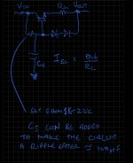
I don't know how your splitter / buffer thingy works because you didn't show it.
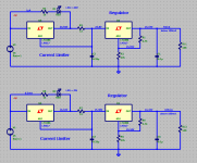
But here's an idea how to do current limiting with standard regulators in front of voltage regulation WITH indicator LED.
Attachments
Last edited:
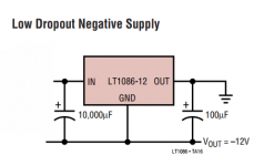
DontHertzMe;6819623There are low dropout regs (e.g. LT1083) said:maybe because negative regulators are not really required, the LT data sheets show how to regulate negative voltages with a positive regulator;
what you define as GND is entirely your choice, a 3-pin regulator doesn't know about GND, it doesn't even have a GND pin, it just compares the voltage difference between Output and Adjust to it's internal Reference ...
Attachments
Sorento said:I don't know how your splitter / buffer thingy works because you didn't show it.
But here's an idea how to do current limiting with standard regulators in front of voltage regulation WITH indicator LED.
R1 choice is a bit high !
Datasheet shows you a current limiting scheme:
Attachments
I spent a couple of hours digging here on DIYAudio and elsewhere, but thank you for the suggested sites - I will dig onward 😀!Keep searching, you will find something.....
I'm happy with all of those things. SMD was a no-go for a while, but since I made a hotplate assembly is much easier. As for complexity, I don't mind complex (within reason - 50 components might be a bit much 😀)How do you feel about using a dual gang (two section) potentiometer to adjust the current limit?
How do you feel about using an opamp, a current sense resistor, and a voltage comparator, per rail?
How do you feel about using parts only available in SMD?
How many components is too many? How complex is too complex?
The actual problem is that the BUF634 has a current limit that I don't want to exceed. I don't foresee short circuits being a problem, it's more for safety reasons - no need to cook the 634 in case something goes awry with a prototype. As for joking about 5%, nope. Surely a tolerance of 95 - 105mA is reasonable?What is the actual problem you are trying to solve? 😕
Please describe it in detail.
You joking? 😀
Just curious, why do you think circuit would go into current limiting?
You expect regular output shorting?
Thank you, that looks great! The splitter circuit in question is here: Virtual Ground Circuits . It's the last schematic toward the bottom of the page.I don't know how your splitter / buffer thingy works because you didn't show it.
But here's an idea how to do current limiting with standard regulators in front of voltage regulation WITH indicator LED.
Good point. I had actually forgotten about flipping positive regulatorsmaybe because negative regulators are not really required, the LT data sheets show how to regulate negative voltages with a positive regulator;

IF you are able to source a dual gang, ten ohm, 1 watt potentiometer ... ... (a big IF) ... ... then this circuit is reasonably simplistic. The pot is there to provide smooth infinitely variable adjustment range (instead of a finite number of discrete steps). You could of course replace it with a DP4T rotary switch and some 1% resistors, if you only wanted four different output current settings. That might actually be an option {holding your nose} if you can't find the dual gang pot in stock anywhere.
_
_
Attachments
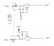
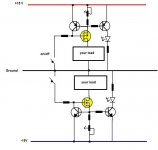
Here is a possibility:
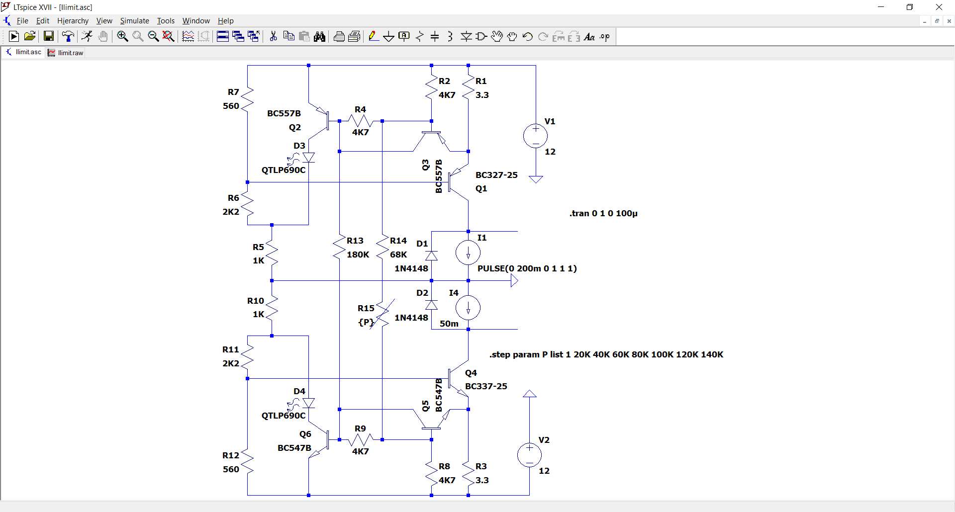
It handles the two polarities, and is adjustable with a single potentiometer from ~0 to 150mA or even more.
Each side has a LED indicating the limitation.
Here it is shown with P varied from 0 to 140K:
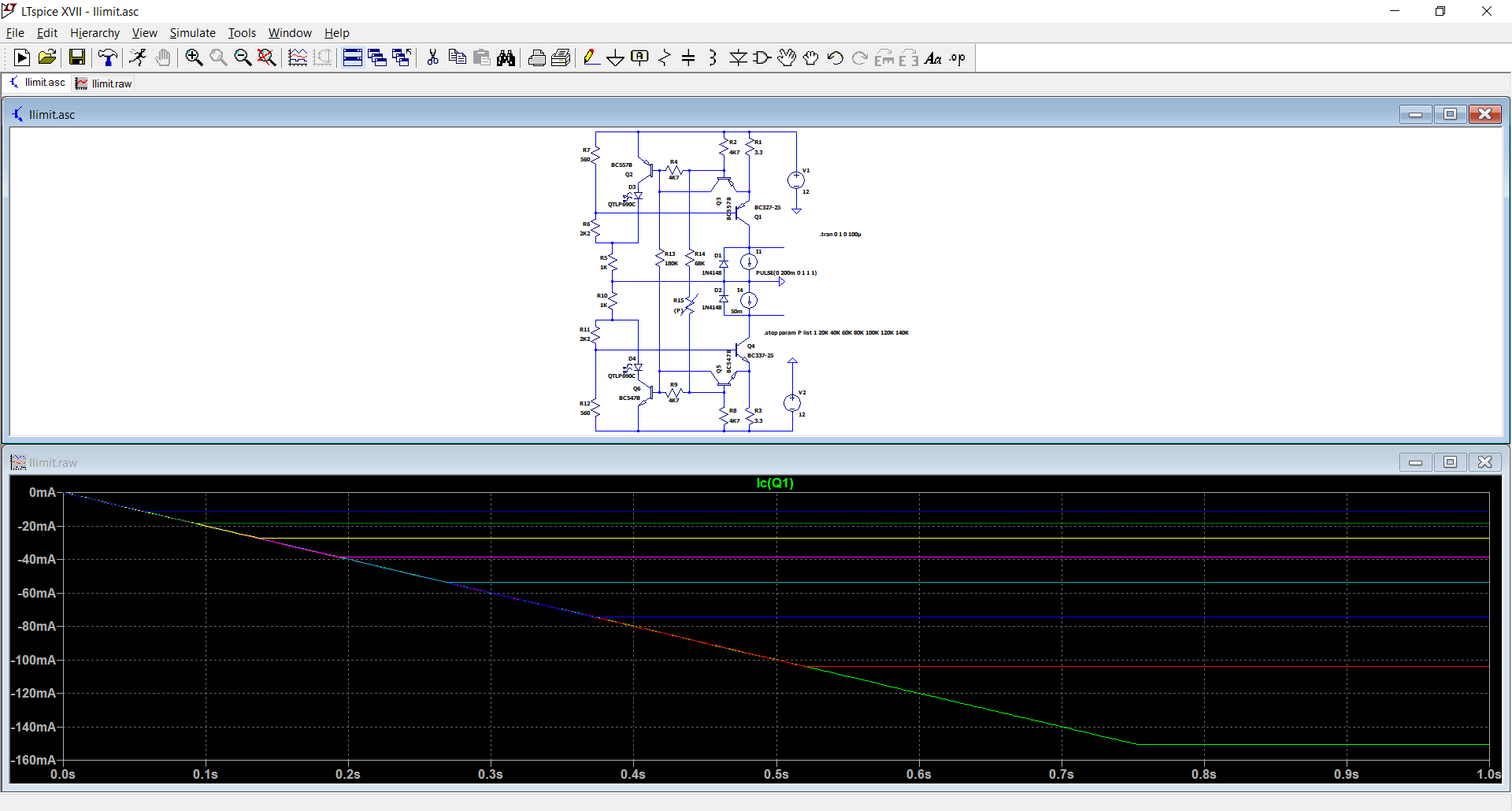
The outputs are on the collectors of Q1 Q4. The diode and current sources are the loads, to illustrate the operation.
It will drop a max of ~0.4V at 100mA output.
It handles the two polarities, and is adjustable with a single potentiometer from ~0 to 150mA or even more.
Each side has a LED indicating the limitation.
Here it is shown with P varied from 0 to 140K:
The outputs are on the collectors of Q1 Q4. The diode and current sources are the loads, to illustrate the operation.
It will drop a max of ~0.4V at 100mA output.
Attachments
IF you are able to source a dual gang, ten ohm, 1 watt potentiometer ... ... (a big IF) ... ... then this circuit is reasonably simplistic. The pot is there to provide smooth infinitely variable adjustment range (instead of a finite number of discrete steps). You could of course replace it with a DP4T rotary switch and some 1% resistors, if you only wanted four different output current settings. That might actually be an option {holding your nose} if you can't find the dual gang pot in stock anywhere.
_
Mark,
To avoid non-vanilla parts, use a 10 ohm resistor with a pot across it.
Something worth considering: if the limiter(s) is to be used with a rail splitter, the primary supply will be unipolar. This means that an overload on a rail will ipso-facto also happen on the other: for example, if a short happens between V+ and GND, the V+ line will see an overcurrent, but this overcurrent will be dumped into the V- line by the rail splitter.
This means that only one limiter is required if it is placed upstream of the rail splitter.
It will of course not be possible to indicate which rail is subjected to an overload without additional means.
If two limiters are placed downstream, they will be able to function individually and indicate which rail causes the problem if they have individual LED indicators
Fantastic, thank you so much everyone! This is really, really useful. Lots for me to experiment with this weekend!
- Home
- Amplifiers
- Power Supplies
- Seeking a mA-range adjustable current limiter for +/- 12V supply