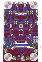
Alright, So I've been designing or rather tweaking the crap out of, the TPA3116 EVM design. That being said, this is only the actual amplifier board, I've still got to do the input filtering and such, and the power supply. PCB is 1oz copper so I tried to make the traces plenty thick enough.
I wanted to post it on here, and let you guys poke holes in it 😛 I've made a few sacrifices in order to achieve the goals, size and a few other little things. Including components available rather than optimal. Solen and Jantzen audio film/foil caps and such. There are many changes that may seem random but I have my reasons 🙂 I'm intending on using school equipment to test this amp, so I, might, have some actual real numbers for you guys once it's fully finished.
will be 24V Power supply, (building it custom) toroidal with 6-7amp capability, and with that, i'll be making it as smooth as possible.
Inductors are coilcraft, I actually have a few options that will fit in the spots I left for them, The caps that are for power conditioning (other than the two 1000uf) are all high pulse low esr film caps, the two main power caps are panasonic low esr high ripple caps, simply put, there is only a few ceramics (most of the smd ones) and the rest are film or film/foil. Before it's mentioned, there are input caps, ^_^ just didn't want to waste the board space, and they will be mounting to another pcb on the other side of them, no need to waste 8"^2 on them. The diode isn't the proper part number in the schematic, just needed the footprint.
The schematic has all the default values that are in the datasheets, some will be changing, some won't, I just made sure that I had the space on the board for the largest of the caps I intended to use. The heat sink is actually mounted using the casing, so no need for holes in the board for it.
Any advice, criticism, etc, is welcomed. Please keep it constructive though 🙂