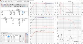
Have simulated a crossover for a TM speaker using Seas W18E001 bass and T25CF002 (Millenium)tweeter. Have the frd. files from seas frequency response graph using vituixCAD, the impedance is measured using DATSv3 on my actual bass and tweeters. How does the crossover seem in Your opinion? Have decent reverse polarity nullout, and the phase seems to align ok...?
Obviously i would have to correct the filter somehow after i measure the drivers in the acctual enclosures, which willl be ported 26 liters. Havent corrected for any baffle step response in the filter.
Obviously i would have to correct the filter somehow after i measure the drivers in the acctual enclosures, which willl be ported 26 liters. Havent corrected for any baffle step response in the filter.
Attachments
Looks pretty sensible to me, but it's possible that having the drivers in the enclosures (with the introduction of diffraction, baffle step, etc) will mean you need to re-work things.
Chris
Chris
*Edit (since I should read more carefully 😉 ).
What Chris said -at the least, simulate the baffle & its diffraction, step loss in VituixCAD. The final measurements will be better of course, but it does give an advance idea.
Otherwise -well, in topology & concept, it's pretty much an approach I personally advocate with metal cone drivers. Low crossover, 4th order electrical to both improve power handling to the tweeter (the Millennium is one of the better tweeters for a low XO anyway) and shunt the W18's primary bell mode sufficiently low in frequency that you shouldn't run into any HD amplification in its passband. I generally prefer this to a lower electrical order + tank or separate notch if it gives enough attenuation. Phase tracking looks reasonable. Polars should be nice & even given that low XO, and the response is tracking a partial Blauert & Laws decline as frequency increases so should have a nice natural balance providing you don't have excessive HF hearing loss. Based purely on what I'm seeing, I like it. Depending on what you're wanting / intending for it, you might want to consider using a slight off-axis response as the baseline (say, 10 degrees off) rather than the on-axis response if you're thinking farfield or general listening. If it's a nearfield monitor, on-axis should be fine, assuming the appropriate toe-in of course. 😉
Last edited:
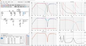
How do i get the baffle step response into the crossover graph in vituixcad? I only seem to be able to load it into the enclosure tool. The baffle is 24 cm wide by 42,5 cm high.
Attachments

Last edited:
If I understand correctly what you did, your simulation is pretty useless. You need first to simulate FR of drivers on your intended baffle, and only then you can start simulating a crossover (you also need to figure out the path difference from the drivers to the mic position, but this is another story).Have the frd. files from seas frequency response graph using vituixCAD, ...
Havent corrected for any baffle step response in the filter.
Simulating a FR on a baffle is easy if you start from an infinite baffle response, unfortunately Seas aren't given that way. I don't know enough Vituixcad to know how to reverse engineer the FR from the Seas baffle.
Ralf
Seas 18cm (7in) driver measurements are taken in a test box with baffle dimensions of 320mm x 215mm, with no horizontal offsent & 104mm down from the top.
DATASHEETS (comments on)
http://seas.no/images/stories/about_seas/TEST_BOXES.pdf (test box dimensions).
I wouldn't describe the simulation as worthless. Some (many) values will change and potentially some topological details as well, but it serves as a rough baseline & gives an idea about what is needed & can work. For example, it demonstrates a 4th order ladder low-pass has a reasonable chance of providing sufficient attenuation of the main cone mode, rather than going with a tank or separate notch (bottomless LC or otherwise).
Last edited:
i am fully aware that this is NOT the final revision of the crossover, and that measurements have to be taken in the intended enclosure. I wrote that in the first post.
But since i am not finished building the enclosures yet this is a starting point.
Useless is doing nothing. 😛
But since i am not finished building the enclosures yet this is a starting point.
Useless is doing nothing. 😛
I concur that doing nothing is useless! But what I was trying to point out is that I would do a complete simulation before building something. You are on the right path to do that. You could end up with something different from what your initial plan was.
Ralf
Ralf
Hey, dont think the worst. Why would you think i would be building this crossover now? I am just simulating, thought that was clear from the pics of the software. Doesnt cost me a single Norwegian oil dollar to do the simulation.
Sorry again, I wasn’t clear enough. I meant you could end up building a different enclosure, or a different baffle, not only a different crossover.
Ralf
Ralf
Yes, it looks good.
Obviously you have spent some time on the sim.
If the FRD and ZMA were from your actual cabinets it hopefully only needs some final shaping and maybe adjustment of the tweeter padding to get it sounding good in your room.
As Scottmoose has pointed out the suppression of the cone breakup of the woofer should be good, and maybe, if your baffle is the same dimensions as the Seas test box for that driver the bass baffle step maybe more than enough already.
The only other observation is the driver positioning and flush mounting the tweeter at least will add some new ripples and change the phase maybe in a good way or in a way where you have to look at different crossover frequencies and slopes. I hope not as your current design it shows a lot of promise.
Interestingly does the 26 litres come from an optimum for that driver or are you chasing a particular deign aim. The group delay is something I would maybe try different box and tuning frequencies to lower it. Maybe go back to the alignments tab and model some different alignments and tuning frequencies.
If you are working from home maybe you can sneak a few minutes in between the day job to investigate.
26 liter comes from this particular driver. If i tune the port the port to 34 hz, i get a much higher group delay than if tuned to 41 hz. But unsure how acurate the DATSv3 measurements are...
Once you have the cabinets build can you take measurements?
Real data is going to be interesting.
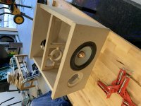
What did you use to shape your brace?
Real data is going to be interesting.
What did you use to shape your brace?
Used a jigsaw for the straight lines, router for sircular lines.
Will measure with dats and measurement mic.
Will measure with dats and measurement mic.
- Home
- Loudspeakers
- Multi-Way
- Seas Excel TM crossover