Hi,
Below are some screen shots of the FRD program for baffle step analysis. I have attempted to use this to optimise the placement of some drivers in an existing box I hope to use.
This post is a bit of a demonstration of what these tools can do. However if anyone knows them better than me and can see any flaws in my approach I would be very interested to hear them. The tools are here:-
FRD Consortium
The box is an old Celstion enclosure I got from freecycle. Its owner had sold the parts off on ebay but the box had no value. It still has its ABR in which I hope to use (Box sim is a different project which has indicated the power handling of this design will be low at about 20W, but thats OK).
The drive units are Seas CA15RLY woofer and a 27TFFC tweeter that have been lying arround, I got them as samples ages ago when working on a comercial design.
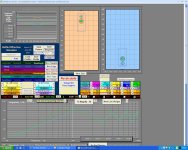
Image 1 shows the drivers vertically aligned in the box (I have left our the ABR as its frequency range is limited to below BSD region) Blue is the tweeter and green the mid / woofer
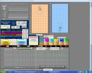
Image 2 shows the drivers offset to what seemed to be the optimum positions after trying lots of options. You can see the improvement in the high end response.
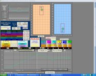
Image 3 shows the drivers offset with a chamfer on the box. My box has a chamfer but it faces in towards the drivers not out. I don't know how this will affect the response, so if anyone does please let me know.
You can clearly see from this that assuming this simulation approaches the real situation by moving the drive units by only a few CM from the center line a very significant improvement in the response can be had basically for nothing. Since it is dificult to correct diffraction problems electrically this seems like a worth while exercise.
Any comments?
Attachments
- Status
- Not open for further replies.


