Hi EaZy,
Use SPLCopy or something similar to convert the manufacturer's SPL and impedance plots to FRD and ZMA files, respectively. You will usually also need something to add a phase angle to the ZMA plots, which I don't right now remember.
Once this is done, take the tweeter and import your new files.
Best,
E
Here is my blog posting about the best uses of a Zobel:
A Speaker Maker's Journey: Crossover Basics - The Zobel
Best,
E
A Speaker Maker's Journey: Crossover Basics - The Zobel
Best,
E
Kudos on the heavy lifting.Here is my blog posting about the best uses of a Zobel:
A Speaker Maker's Journey: Crossover Basics - The Zobel
Best,
E
So I finally found the frd and zma files for my 27TBFC/G tweeter and just have played with XSIM to compare it with the A26 stock kit.
Here is a simulation of the A26 as sold as a kit with the T35 exotic tweeter :
I first have a question regarding the voice coil resistance and inductance, shouldn't we take them in account in the simulations?
On the graph below I made one simulation with and without them (the light blue curve is the model which does not take them into account, the dark blue take these values into account) :
Then I found out that my crossover seems really to dampen way too much the high frequencies (blue curve):
A good balance would a be obtained according to the simulation without any resistor on the tweeter.
However I tried many combinations in real life and can tell you that any resistor in series with my tweeter with a value below 8 ohms or above 12 ohms makes the system really inaudibe.
Finally an almost flat frequency response could be attained using the filter below :
Or modifying the sensitivity of the speakers (lowering the woofer or increasing the tweeter by 5 dB)
What do you think about it? What is the cause of such a discrepancy betwen the simulation and the actual speakers I have at home?
Here is a simulation of the A26 as sold as a kit with the T35 exotic tweeter :
An externally hosted image should be here but it was not working when we last tested it.
I first have a question regarding the voice coil resistance and inductance, shouldn't we take them in account in the simulations?
On the graph below I made one simulation with and without them (the light blue curve is the model which does not take them into account, the dark blue take these values into account) :
An externally hosted image should be here but it was not working when we last tested it.
Then I found out that my crossover seems really to dampen way too much the high frequencies (blue curve):
An externally hosted image should be here but it was not working when we last tested it.
A good balance would a be obtained according to the simulation without any resistor on the tweeter.
However I tried many combinations in real life and can tell you that any resistor in series with my tweeter with a value below 8 ohms or above 12 ohms makes the system really inaudibe.
Finally an almost flat frequency response could be attained using the filter below :
An externally hosted image should be here but it was not working when we last tested it.
Or modifying the sensitivity of the speakers (lowering the woofer or increasing the tweeter by 5 dB)
What do you think about it? What is the cause of such a discrepancy betwen the simulation and the actual speakers I have at home?
Last edited:
Um, the very first thing I think you should do is understand Ohm's law. Your understanding of resistors is incomplete and this will help you understand what the other parts are doing.
When you are done with that, read this:
A Speaker Maker's Journey: Crossover Basics - Impedance
And then read this:
A Speaker Maker's Journey: Crossover Basics - Driver Response
And finally this:
A Speaker Maker's Journey: Crossover Basics - The Zobel
Best,
E
When you are done with that, read this:
A Speaker Maker's Journey: Crossover Basics - Impedance
And then read this:
A Speaker Maker's Journey: Crossover Basics - Driver Response
And finally this:
A Speaker Maker's Journey: Crossover Basics - The Zobel
Best,
E
Voice coil resistance and inductance are already accounted for in their impedance curves and frequency response (FRD) data, you shouldn't add them in again.
Um, the very first thing I think you should do is understand Ohm's law. Your understanding of resistors is incomplete and this will help you understand what the other parts are doing.
E
What makes you say that eriksquires? (no offense, but I think I used this law more than you think during my physics studies, so maybe you don't need to start with such a condescending attitude towards someone you don't know).
I just want to get an appropriate answer from a experimented person on a very applied situation.
Thanks for the links however, I started reading it and find it is quite interesting.
Bwasio, thanks for your clear answer on my first question.
OK I just started a new thread for my speakers not to pollute this one.
It explores the 27TBFC/G as a much cheaper and serious concurrent to the T35.
See here : A26 w/ 27TBFC/G thread
Thanks for helping me in improving my filter if possible!
It explores the 27TBFC/G as a much cheaper and serious concurrent to the T35.
See here : A26 w/ 27TBFC/G thread
Thanks for helping me in improving my filter if possible!
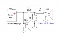
As agreed with Erik, I have completed the data files of post #2 with phase angle that's contained in the zipped file. This is the sim of the original Seas A26 kit units. To fit one's own taste, tweeter padding can be easily modified.
Attachments

Lojzek means, he was kind enough to take my dirty work and clean it up.
Thank you very much! I hope this helps future A26 investigators, modders and hobbyists. 🙂
Best,
E
Thank you very much! I hope this helps future A26 investigators, modders and hobbyists. 🙂
Best,
E
BTW, the coil in the tweeter circuit is not part of the A26 kit. It is a very nice fix by Lojzek. 🙂
Best,
E
Best,
E
Hi Everyone,
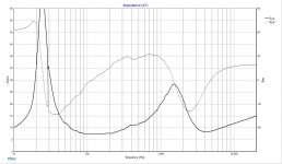
Just wanted to share an XSim model of the A26. It's reasonably accurate, but the raw driver data comes from images, so the impedance is pretty ragged.
Anyway, I though it might be a good reference in case anyone was curious, or a newbie wanted to play around with XSim or what not.
Hi Erik,
can you please tell me from which document you extracted the data?
Actually I just notices the woofer's frd seems quite different from the one which is on seas spec sheet...
Erik's FRD :
An externally hosted image should be here but it was not working when we last tested it.
Seas spec sheet :
An externally hosted image should be here but it was not working when we last tested it.
Hi Eazy,
As I recall, the process with SPLCopy was pretty tedious. If you feel you have a better FRD, please post it. I never meant to own the design, I put a little bit of work into this, and thought it would be fun to share and play with others. I am happy to see it used and improved upon.
It is certainly possible I messed up something like the SPL levels when I was converting from the image to FRD file.
Best,
E
Doesn't matter that much for builders should investigate the tweeter padding anyway which should be a primary concern.
Distance from mic to speaker and speaker to wall can make that much difference, as can even just unit to unit variation. Speaker driver behavior is no where near as consistent as, say, electronic component behavior.
Hi apparently the frd file correspond to the measurement found on this page :
Seas A26 - April 2013 - Loudspeakermagazine 2013 | Loudspeakerbuilding
where the reviewer made the measures at 1.5 meter (not in standard conditions). He inculdes the phase too, whereas SEAS' spec sheet doesn't. The tweeter padding can have an influence on phase so it would be more accurate to decrease the A26RE4 sensitivity of about 2 dB in XSim file to account for the real sensitivity measured in std conditions by SEAS.
All these issues can be avoided making real measurements, instead of loosing time playing with sims based on data you cannot trust...🙄
- Status
- Not open for further replies.
- Home
- Loudspeakers
- Multi-Way
- Seas A26 Kit - Modelled in XSim