Hi Everyone,
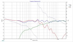
Just wanted to share an XSim model of the A26. It's reasonably accurate, but the raw driver data comes from images, so the impedance is pretty ragged.
Anyway, I though it might be a good reference in case anyone was curious, or a newbie wanted to play around with XSim or what not.
Best,
Erik
Just wanted to share an XSim model of the A26. It's reasonably accurate, but the raw driver data comes from images, so the impedance is pretty ragged.
Anyway, I though it might be a good reference in case anyone was curious, or a newbie wanted to play around with XSim or what not.
Best,
Erik
Hi,
but what are the 30,60,90° curves.... a 25 cm cone Sd means it beginns to be not pistonic around 1 000 Hz and start beaming jut a little above !
Maybe we could expect than a little 3 db dip off axis à la BBC study between 1 000 and 2 000 Hz is liked ?
Erik, did you ever listened this Kit ?
Aha, Troels would be flaten the impedance curve around the XO points as he did for the Proac D15 .... and maybe uses an AUDAX 35 mm driver... without the 10 ohm resistor in serie !
The four layers voice coils of the A26 driver certainly makes not the best drivers unit around, no ?
Last edited:
Hi Eldam
Im just posting work I did for fans. Im not recommendong the kit. If you want more data I suggest you make one yourself and post it here.
Erik
Im just posting work I did for fans. Im not recommendong the kit. If you want more data I suggest you make one yourself and post it here.
Erik
Hi Erik,
Calm down please. I'm not critising you or your work (and here the SEAS worl as well) but just imputed one can't judge an XO on axis.
regards
Calm down please. I'm not critising you or your work (and here the SEAS worl as well) but just imputed one can't judge an XO on axis.
regards
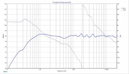
Quick improvement by adding 0.68 mH as a 2nd order to the tweeter
Significantly better tweeter power handling, on-axis response,
driver phase still being ok. The XO point is pretty much defined
by the woofer's LP response, the only issue left being the tweeter's
HP and padding.
Significantly better tweeter power handling, on-axis response,
driver phase still being ok. The XO point is pretty much defined
by the woofer's LP response, the only issue left being the tweeter's
HP and padding.
Attachments
Howdy Erik,
your selection is just the right kind for novice builders. It has very decent
bass capabilities and is simple enough to execute. A vintage style loudspeaker
of the 70's.
your selection is just the right kind for novice builders. It has very decent
bass capabilities and is simple enough to execute. A vintage style loudspeaker
of the 70's.
Lojzek,
Thank you! 🙂 I have been posting on various forums links to the XSim files for the LM-1 too, I hope they become useful tools for many newbies.
Best,
Erik
Thank you! 🙂 I have been posting on various forums links to the XSim files for the LM-1 too, I hope they become useful tools for many newbies.
Best,
Erik
So the acoustic distance used for the woofer was estimated based on the published FR of the completed kit and interferometry. 🙂 In other words I moved the distance until my model matched the published FR. It's easily possible I made a mistake.
Still, I like Lojzek's approach a great deal. I had tried to get fancy, by doing a 2nd order low pass and high pass filters, and that just went belly up. Lojzek's idea to just add a coil is pretty masterful.
So, adding an 0.91 mH coil I get to nearly perfect phase matching at the Xover point, but not the most symmetrical inverted response. However, as noted, this is just in simulation. The actual acoustic distance needs to be known. 🙂
Best,
Erik
But the phase curves for the impedances are impossible! 0 degrees flat, with those kinds of magnitude gyrations?
(Yeah, I know, I should get around to adding a Hilbert impedance phase curve extractor.....)
(Yeah, I know, I should get around to adding a Hilbert impedance phase curve extractor.....)
Bill,
Would you please?? 🙂
Unfortunately this is the best I could do given that I was going from pictures. The LM-1 files however have it all. 🙂 Except the port contributions....
Erik
Would you please?? 🙂
Unfortunately this is the best I could do given that I was going from pictures. The LM-1 files however have it all. 🙂 Except the port contributions....
Erik
Erik, Bill,
Many thanks both. I have the A26 drivers in a much larger BR cabinet, and haven't yet played with Xsim, so this is perfect.
I'll post my effort and would appreciate constructive criticism 🙂
James
Many thanks both. I have the A26 drivers in a much larger BR cabinet, and haven't yet played with Xsim, so this is perfect.
I'll post my effort and would appreciate constructive criticism 🙂
James
Hi Sharpi,
You are most welcome for my part. 🙂 Please enjoy yourself.
If you can add real impedance curves it would be even better.
You are most welcome for my part. 🙂 Please enjoy yourself.
If you can add real impedance curves it would be even better.
Not a substitute for a real curve, but I've found this utility extraordinarily useful for extracting high resolution curves from images when the raw data is not available. Perhaps you've already used a similar tool to extract, but if not you might want to give this one a whirl. I'm in the process of building the A26, so will be following this thread.
BK
BK
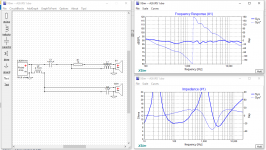
Ground points are free you know. Use them liberally to reduce wiring.
Next, check your phase. Invert S1 and examine the FR plot. Should have a nice icicle form at the crossover point.
Turn off the system curve, and turn on S1 and S2, with phase to examine phase match directly.
Best,
Erik
Next, check your phase. Invert S1 and examine the FR plot. Should have a nice icicle form at the crossover point.
Turn off the system curve, and turn on S1 and S2, with phase to examine phase match directly.
Best,
Erik
Now is a good time to point out that those who build the A26 with the minimum crossover really like it that way. Everything I'm discussing from here especially forward is just for fun, but not a recommended right way.
Here's a good example from the LM-1 of what a close to ideal inverted FR should look The blue line is the normal version, the red line is what happens when you invert the tweeter on the LM-1. For more, go here.
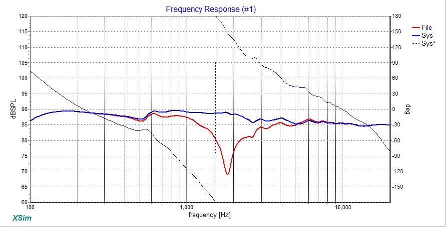
Here's a good example from the LM-1 of what a close to ideal inverted FR should look The blue line is the normal version, the red line is what happens when you invert the tweeter on the LM-1. For more, go here.
Last edited:
Thinking of building this kit, would it suit a smallish carpeted living room paired with Tubleab SSE (single ended) running KT88's...about 8 watts? Am currently using Dynaudio Audience 52 standmounts (4ohm 87db) and the amp even with this speaker goes loud enough... I just think the easier load would be lapped up by the SE?
- Status
- Not open for further replies.
- Home
- Loudspeakers
- Multi-Way
- Seas A26 Kit - Modelled in XSim