Hi All,
Back from the woods and dug out found my original 'sketches' for this filter.
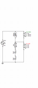
As you can see we all forgot that you need to double the capacitance when series coupling the caps..😉.
So please use 2x22μF caps in this particular filter!
The DC circuit is now correct as per the last post @planet10 . You can also use one 9V-6LR61 battery or you can series couple 2 of those to get to 18V,
we thought this had a very slight sonic benefit. (The 18V is a tip from some JBL/Altec enthusiasts in Japan, Greg Timbers used 9V for his JBL statement speakers.)
It should be noted that the charged circuit also measured better than the equivalent 'standard' filter but, this could be due to happenstance because of luck of better matching values due to tolerances.
Here's a qoute from 2013 by Lynn Olson in this forum explaining the why's and how's:
"The clever part of the charge-coupled circuit is the 100K to 1M resistor in series with the battery. The resistor can be this high because the DC leakage of modern capacitors approaches zero, and all the battery is doing is polarizing the cap-pair in one direction.
To recap, the JBL "charge-coupled circuit" replaces a single cap with a pair of series-connected caps of twice the value of the original single cap, the center-point between the cap-pair is attached to a battery in series with a 100K to 1M resistor, and the other side of the battery is attached to circuit ground. This polarizes both caps to the DC voltage of the battery, so the caps never go through zero-crossing. 9V is a better choice than 1.5V batteries, since loudspeaker-level signals fairly frequency pass through the 1.5V threshold, but 9V is getting pretty loud.
A single battery can polarize all of the cap-pairs in a complex crossover by the simple expedient of a separate 100K to 1M resistor going to the center point of each cap-pair in the crossover. The resistances are so high relative to loudspeaker (and crossover) impedances that the crosstalk between sections is negligible."
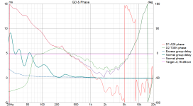
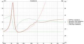
Of course, and as it should for such a simple filter, GD is very low and the impedance curve also presents a very uncomplicated load to the amp.
Again, please note that this filter is optimized for off-axis use; for best results put speakers parallel with the front wall and keep the speakers close to the walls (<40cm) .
Best
-a
Back from the woods and dug out found my original 'sketches' for this filter.
As you can see we all forgot that you need to double the capacitance when series coupling the caps..😉.
So please use 2x22μF caps in this particular filter!
The DC circuit is now correct as per the last post @planet10 . You can also use one 9V-6LR61 battery or you can series couple 2 of those to get to 18V,
we thought this had a very slight sonic benefit. (The 18V is a tip from some JBL/Altec enthusiasts in Japan, Greg Timbers used 9V for his JBL statement speakers.)
It should be noted that the charged circuit also measured better than the equivalent 'standard' filter but, this could be due to happenstance because of luck of better matching values due to tolerances.
Here's a qoute from 2013 by Lynn Olson in this forum explaining the why's and how's:
"The clever part of the charge-coupled circuit is the 100K to 1M resistor in series with the battery. The resistor can be this high because the DC leakage of modern capacitors approaches zero, and all the battery is doing is polarizing the cap-pair in one direction.
To recap, the JBL "charge-coupled circuit" replaces a single cap with a pair of series-connected caps of twice the value of the original single cap, the center-point between the cap-pair is attached to a battery in series with a 100K to 1M resistor, and the other side of the battery is attached to circuit ground. This polarizes both caps to the DC voltage of the battery, so the caps never go through zero-crossing. 9V is a better choice than 1.5V batteries, since loudspeaker-level signals fairly frequency pass through the 1.5V threshold, but 9V is getting pretty loud.
A single battery can polarize all of the cap-pairs in a complex crossover by the simple expedient of a separate 100K to 1M resistor going to the center point of each cap-pair in the crossover. The resistances are so high relative to loudspeaker (and crossover) impedances that the crosstalk between sections is negligible."
Of course, and as it should for such a simple filter, GD is very low and the impedance curve also presents a very uncomplicated load to the amp.
Again, please note that this filter is optimized for off-axis use; for best results put speakers parallel with the front wall and keep the speakers close to the walls (<40cm) .
Best
-a
Attachments
Last edited:
Basically all woofers need a little break in...couple of hours. Say 10 hours should do the trick. So by the time you read this. They are probably run in.In your experience, is there any break in period with these drivers?
Thanx airvoid. Next rev for QC. Please check point #2, i added a bit i hope is right … as iunderstand it, same difference between SE & PP OPTs around the zero crossing, i hope the word “Hysteresis” is appropriate.

dave
dave
This is a little piece I wrote for our commercial project. Most of this is information directly stolen/sourced from Greg Timbers 😇. He is the father of this tech.CHARGE-COUPLED LINEAR TECHNOLOGY
Charge-Coupling works in basically two ways:
- By controlling and utilizing the capacitors piezoelectric nature
- By biasing the capacitor above zero crossing
The benefits of Charge-Coupled Linear Technology lies in what a charge bias does to the capacitors themselves. When an audio signal passes through a capacitor it changes polarity and passes through zero volts - the current flow changes direction. But it does not do that instantly. Due to the dielectric absorption of the capacitor it ”remembers” the previous state and therefore resists change. This leads to a blurring of transients in the drive signal, a highly audible distortion.
The impedance of a capacitor is dependent on the signal frequency and the physical and electrical nature of the capacitor. Factors that determine the sound quality of capacitors in a audio crossover network include:
1. The material composition of the conductive plates
2. The material composition of the dielectric
3. The tightness of the winding of the capacitor.
A pair of series coupled capacitors in the A35 filter has a voltage applied to its center point.
By doing this, the individual capacitors are charged, biasing the dielectric gap above or below ground potential without DC appearing outside the confines of the capacitor pair. When this occurs, the music signal driving through the paired capacitors never cross the dielectric zero point, which results in a far more linear operation. This is analogous to the difference between ’Class A’ and ’Class B’ amplifier operation.
Piezoelectric Control
It has been established that capacitors that are more tightly wound have a better transient response than those who are wound more loosely. Applying a constant voltage to a capacitor results in a piezoelectric effect, which physically squeezes the capacitor tighter. At higher power levels the alternating current of an audio signal can cause a capacitor to exhibit substantial piezoelectric behavior, causing it to expand and contract with the changing voltage.
By applying a constant voltage the capacitors are pre-squeezed effectively minimizing fluctuations in transient performance and effectively reducing deterioration of linearity.
Bias Control
The method of charge-coupling - biasing over zero crossing - has an even greater effect than controlling piezoelectric effect.
By biasing the capacitors so that the signal does not reverse current flow through the capacitor, zero crossing distortion is eliminated.
Charge-coupled capacitors constantly operate within their linear range, so time delay and dielectric absorption is neutralized , resulting in less phase distortion and a more musical presentation.
Last edited:
It is to be expected that it sounds better when the crossover cut is moved much lower, it is a better solution. The A26 cannot compete successfully with the T35 in the mid-range. The original SEAS crossover is an improvisation.
You also have to be extremely careful with those Jantzen caps, the casing edges are conductive, it’s an aluminum tube, so make sure none of your wires or resistors are touching the capacitor casing or you will have shorts.

More of an hommage to the original A25, which possess a similar simple crossover. In the present case, how down is the crossover?It is to be expected that it sounds better when the crossover cut is moved much lower, it is a better solution. The A26 cannot compete successfully with the T35 in the mid-range. The original SEAS crossover is an improvisation.
- Home
- Loudspeakers
- Multi-Way
- SEAS A26 Devore Style Build