Hi folks,
with new, fresh energy I want to try a new idea and would need the old Threshold-schematics, some time ago online in NPs public directory (gone with the new website). They're the late Threshold schematics called
thr_os89.tif and thr_fe89.tif
Since I don't want to put my email here, please drop me a short line if I could have them from you! I will immediately reply!
Thank you very much! All the best, Hannes
PS: oh and some good advice: ALWAYS download ALL stuff from the great emperor.
Oh yes I know!
And then the world's cutest treasure box will be online again 😀
However I currently have some time at hand, so I would be glad if somebody could help me with this!
All the best and have fun! Hannes
And then the world's cutest treasure box will be online again 😀
However I currently have some time at hand, so I would be glad if somebody could help me with this!
All the best and have fun! Hannes

Zen Mod said:
Does the Threshold SA series power amp can be cloned? If so which point at the front end should be connected with the Common Point for Parallel Mono Amp at the output stage?
Does the Threshold SA series power amp can be cloned?
Sure! I'm currently thinking a bit about it.
Have fun, Hannes
h_a said:
Sure! I'm currently thinking a bit about it.
Have fun, Hannes
Hi Hannes
So which point at the front end should be connected to the Common Point for Parallel Mono Amp at the output stage?
I am also interesting in the SA series power amps.
Thanks
The frontend has nothing peculiar to do with that.
Don't worry about this now and work on a single amp first. Or is the additional wattage really that hard needed?
Have fun, Hannes
Don't worry about this now and work on a single amp first. Or is the additional wattage really that hard needed?
Have fun, Hannes
buying any Treshold for reasonable money and refresh it is one thing , certainly more than reasonable and rewarding ;
making one from scratch ....... I'm sure that Papa will tell you that making one of his later designs is better investment ......... labor and funds/sound wise ......
making one from scratch ....... I'm sure that Papa will tell you that making one of his later designs is better investment ......... labor and funds/sound wise ......
Treshold for reasonable money
Ah yes. But that's another competition. Ebay shows only ridiculous prices...
Alternatively one of the Alephs would be much easier to clone and certainly sound even better. Maybe you could even buy pcbs from other members? Would facilitate your project a lot.
Have fun, Hannes
h_a said:The frontend has nothing peculiar to do with that.
Don't worry about this now and work on a single amp first. Or is the additional wattage really that hard needed?
Have fun, Hannes
Hi Hannes
Actually I already have all the parts for the front end. I really concern about the connection points between the front end and the output stage. That is why I have been putting this project on hold until everything is clear before I go further.
Attachments
Dear fellow,
you're missing much more than that.
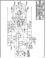
Just look at the front end pins! You will note that crucial parts are not contained in the front end schematic - I mean crucial for full operation of a real amp (not topology wise).
The easy things are input impedance (voltage divider at the input), the bias pot for the VBE-multiplier and offset adjust.
The not so easy one is frequency compensation. For that one you will likely need an oscilloscope and a bit of fiddling to get it right. Or you could give simulation a go.
Please don't get me wrong, but I think you're not yet up to cloning this amp on your own.
Why don't you build one of those cute Alephs first?
Have fun, Hannes
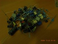
PS: by the way, not a nice way to store parts 😱
you're missing much more than that.
Just look at the front end pins! You will note that crucial parts are not contained in the front end schematic - I mean crucial for full operation of a real amp (not topology wise).
The easy things are input impedance (voltage divider at the input), the bias pot for the VBE-multiplier and offset adjust.
The not so easy one is frequency compensation. For that one you will likely need an oscilloscope and a bit of fiddling to get it right. Or you could give simulation a go.
Please don't get me wrong, but I think you're not yet up to cloning this amp on your own.
Why don't you build one of those cute Alephs first?
Have fun, Hannes
PS: by the way, not a nice way to store parts 😱
h_a said:Dear fellow,
you're missing much more than that.
Just look at the front end pins! You will note that crucial parts are not contained in the front end schematic - I mean crucial for full operation of a real amp (not topology wise).
The easy things are input impedance (voltage divider at the input), the bias pot for the VBE-multiplier and offset adjust.
The not so easy one is frequency compensation. For that one you will likely need an oscilloscope and a bit of fiddling to get it right. Or you could give simulation a go.
Please don't get me wrong, but I think you're not yet up to cloning this amp on your own.
Why don't you build one of those cute Alephs first?
Have fun, Hannes
PS: by the way, not a nice way to store parts 😱
Hi Hannes
Are you sure it is not a complete schematic? I have the service manual of the SA series and in the manual there is also a layout of the pcb for the front end. The parts on the schematic are same as those on the pcb layout.
Attachments

Ah I see you're talking about the original '89 frontend! I was referring to the '90 version that never went into series (that I'm interested in). Sorry!
Of course that's a different story - however it has also unknowns as the 'to stasis collector' connection. I did not bother to look closer at that, but it's probably easy to figure out.
Have fun, Hannes
Of course that's a different story - however it has also unknowns as the 'to stasis collector' connection. I did not bother to look closer at that, but it's probably easy to figure out.
Have fun, Hannes
- Status
- Not open for further replies.
- Home
- Amplifiers
- Pass Labs
- Searching for Threshold schematics once online