Hi,
It seems that I need some new speakers and they need to be able to stand near by a back wall and to be no bigger than 35x40x110 cm. (14x16x43.5 in)
No demand for high SPL, but rather for 25-30hz@0 db or as close to that as possible.
Here I have access to TB speakers and those: VKN 12211/311 - they are kind of legend here... and cost about 47$ - don't be mislead by the price - it's manufacturer's price for the local market, in Scandinavia they are sold under the Gamma brand and are asked much more appropriate prices 🙂
Generally I can deal with crossover and tweaking, but I can't deal with enclosures.
I must say that I'm not an enemy to the correction circuits - such as RL in parallel for equalizing the low end.
It would be great if I use 2x12 in per speaker and a fullrange.
With the given size the internal volume would be about 100-110 liters when the bracing is accounted - if it is possible it to be smaller it would be better.
Also I'm kinda not fluent, but used to the Edge baffle and OB calculator so I can make an OB for the fullrange, but that would reduce the height of the enclosure for woofers.
The questions are:
- Is the data from the given link enough to calculate an enclosure;
- which TB speaker in the range up to 60$ per speaker should I use for best results and in what enclosure - sealed or OB (I like OB)
- what should be the enclosure for the woofers - vented (a hole somewhere only to decrease compression resistance such as the ones big Infinity's have), BR or sealed? (tend to prefer sealed)
Haven't used a FR yet - only tried some garage made and wasted some plywood on it without sonic success.
Another consideration would be that the FR from TB that you recommend me is a close in size to some Fostex driver, because if it turns out the project to be success I might go to Fostex... if Fostex is really better than TB of course.
The aim is SQ, balanced sound with good low's and good bright solo drums.
Last edited:
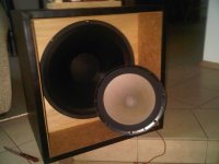
Hey T101,
They look good.
You need T/S parameters and the frequency curves.
You can also have them measured if you like them.
You say you have a link to the full set (parameters) under another brand?!
You can always play with them to have a feeling.🙂
You need Sd, Rdc, Mms, Fs (a measured parameter would be good)... also (the same) for the curves when doing the xover for an accurate design. For both drivers (2xLow/Mid).
Here is where I am now:
I'm probably gonna use the 8 ohm version of the 12 inch VKN - single per speaker for now.
It has QTS of 0.58 and VAS of 264L
So a 145-160 litre Aperiodic enclosure seems sufficient to bring the f8 to 25-28 hz and the f3 to under 40hz - pretty decent for me.
From what I have researched I have chosen that TB driver: http://www.tb-speaker.com/detail/1208_03/w3-871sc.htm
Straight response - no dips and peaks and 87 db sensitivity.
Since the bass is rated as 91 db sensitivity and a first order series crossover at ~1250 hz is chosen, this leaves us in danger of shouting mids...
So I calculated the baffle step with EDGE and designed a correction circuit for the bass only.
That way we end with 87+6 db=93 db sensitivity for the full range - maybe it'll receive an ohm or two series attenuation, maybe not - depending on listening impressions and/or measurements.
And we'll have the baffle step of the bass attenuated with the L2-R3 circuit
+ A bonus - some -1 db@50 hz and -2db@80 hz which will bring up some more low bass.
Any crossover advices and comments are very welcome!
I'm still considering the enclosure of the TB - whether it to be a very open Aperiodic, sealed, aperiodic with whole back an aperiodic vent, aperiodic with parts of the three sides vented or an OB... and what volume...
Here is a link to Sansui speakersSansui Speakers
I am quite tempted to make some variation of the LM series tweeter enclosure:

It actually occurs that I have come to the idea of building some kind of variation of the Sansui LM speakers - I found that after I made the sketch of the enclosure and began thinking about the enclosure for the full range...
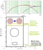
Enclosure is the fourth attachment - note that the lilac net is an aperiodic vent and it should be on the other side too and on the top with the same depth too... - I didn't finish the drawing...
Some question about the aperiodic vent placement, orientation and size arise too. I consider 15x30 cm (6x12 in) either in the low part of the back or of the front... should it be horizontally or vertically oriented?
Absolutely any comment or advice is welcome and appreciated as I don't know much about the enclosures!
p.s. don't mind the mic position at the screenshots, I have set the distance to 100m so the position doesn't play a role in the response plot.
I'm probably gonna use the 8 ohm version of the 12 inch VKN - single per speaker for now.
It has QTS of 0.58 and VAS of 264L
So a 145-160 litre Aperiodic enclosure seems sufficient to bring the f8 to 25-28 hz and the f3 to under 40hz - pretty decent for me.
From what I have researched I have chosen that TB driver: http://www.tb-speaker.com/detail/1208_03/w3-871sc.htm
Straight response - no dips and peaks and 87 db sensitivity.
Since the bass is rated as 91 db sensitivity and a first order series crossover at ~1250 hz is chosen, this leaves us in danger of shouting mids...
So I calculated the baffle step with EDGE and designed a correction circuit for the bass only.
That way we end with 87+6 db=93 db sensitivity for the full range - maybe it'll receive an ohm or two series attenuation, maybe not - depending on listening impressions and/or measurements.
And we'll have the baffle step of the bass attenuated with the L2-R3 circuit
+ A bonus - some -1 db@50 hz and -2db@80 hz which will bring up some more low bass.
Any crossover advices and comments are very welcome!
I'm still considering the enclosure of the TB - whether it to be a very open Aperiodic, sealed, aperiodic with whole back an aperiodic vent, aperiodic with parts of the three sides vented or an OB... and what volume...
Here is a link to Sansui speakersSansui Speakers
I am quite tempted to make some variation of the LM series tweeter enclosure:
It actually occurs that I have come to the idea of building some kind of variation of the Sansui LM speakers - I found that after I made the sketch of the enclosure and began thinking about the enclosure for the full range...
Enclosure is the fourth attachment - note that the lilac net is an aperiodic vent and it should be on the other side too and on the top with the same depth too... - I didn't finish the drawing...
Some question about the aperiodic vent placement, orientation and size arise too. I consider 15x30 cm (6x12 in) either in the low part of the back or of the front... should it be horizontally or vertically oriented?
Absolutely any comment or advice is welcome and appreciated as I don't know much about the enclosures!
p.s. don't mind the mic position at the screenshots, I have set the distance to 100m so the position doesn't play a role in the response plot.
Attachments
Last edited:
If you say the woofer is a 91dB (in a 2-Way), then 91dB-~4(BSC)=87dB to match up with the 87dB mid/high frequency, what is very fine or I'm missing something. You probably can bring the xover to the 400Hz.That way we end with 87+6 db=93 db sensitivity for the full range...
The woofer looks nice. I don't believe the 25Hz (Fs) thing, should be nice, close to the 23Hz of the Kef B139. You should measure them yourself for adequate sized boxes.
Last edited:
If you say the woofer is a 91dB (in a 2-Way), then 91dB-~4(BSC)=87dB to match up with the 87dB mid/high frequency, what is very fine or I'm missing something. You probably can bring the xover to the 400Hz.
The woofer looks nice. I don't believe the 25Hz (Fs) thing, should be nice, close to the 23Hz of the Kef B139. You should measure them yourself for adequate sized boxes.
You are not missing anything, the woofer and the fullrange have 4 db difference in the sensitivity. Having in mind that they will be on the same baffle, leads to the conclusion that the woofer will receive a 6 db BSC and the tweeter wiil receice nothing or only a 1-2 ohm resistor.
I prefer the 6 db BSC, because that will lower the 45-50 hz level with ~1db and the 80 hz level with 2 db and so on... - thus low bass will be elevated from -8 db at 26-28 hz to -6 at 26-28 hz... which is quite good... and the -3 db point will occur at around 34-36 hz... So this will be a 34 to 21 khz @-3db @91 db@1w speaker - quite high standard for a garage made DIY costing around or less than 300$ in total.
Of course I'll have them measured. The 25hz resonance is not under doubt - they are an old design and quite well known here... kind of a legend.
And they really go to 4 khz - there are designs where the 12 inch VLD is paired directly to those VLD 40
Today I placed an order for a pair and now we wait... and I'm still not knowing anything about Aperiodic enclosures...
EDIT: http://www.lautsprechershop.de/tools/index_en.htm?/tools/t_box_closed_en.htm is this a reliable calculator? I'm asking because I'm not keen with "Bass Box".
Can someone who knows "what and how" run a simulation of aperiodic with the 8 ohm version this http://vissokogovoriteli.bg/products/VKN-12211_311.htm
Aperiodic would be a short and relatively small vent or a larger sealed box equal to a smaller aperiodic??? Both overdamped...
We're aiming for 140-160L actual box internal volume.
Last edited:
Re the VKN drivers you posted.
A single 8 ohm would give you good sealed butterworth response in a 540 litre box.
The 4 ohm, a single would fit into 100 litre, F3 ~43 Hz, F10 ~24 Hz.
2 drivers would require 2x the volume.
dave
A single 8 ohm would give you good sealed butterworth response in a 540 litre box.
The 4 ohm, a single would fit into 100 litre, F3 ~43 Hz, F10 ~24 Hz.
2 drivers would require 2x the volume.
dave
Thank you! It is always better to have an opinion from someone "who have been there".
Some questions have arisen.
What about 2x4 ohm in series in 200L sealed or 120-150L Aperiodic enclosure?
And what about a single 4 ohm in ~100L and Aperiodic?
The other options are not considered, because they are way too non practical.
If it is possible to achieve the 540L response of the 8 ohm version with under 200L Aperiodic enclosure it would be best. But is it possible?
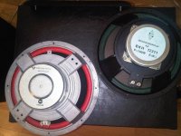
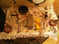
The first 4 12 inch woofers are present.
Rather old ones in perfect condition two have served dutie in 50L sealed enclosures and two have served in ~80-100L bass reflex. The difference in the suspension stiffness is easily detectable by pushing the membranes.
Now we wait for the 4 brand new ones to arrive.
We (me and a friend of mine who is the owner of those for the last 17 years) were hoping for the AlNiCo versions, but they are standard ceramic magnet versions.
Never the less they have absolutely beautiful and balanced sound, they even reproduce cymbals 😱 - no surprise there are designs where those are paired directly to a ribbon tweeter. A true super extended range paper cone woofer! They are rated 25hz-4khz with average of 91 db@1w spl between 100hz and 4khz.
Paper membranes in paper's natural color. The new ones have the same membranes in theory, but are painted black.
When the new 4 arrive, we'll have all 8 woofers measured and see which ones suite what enclosures. For now i am even more convinced that the 1250 hz first order series crossover is the ONE for those! 🙂
I am very happy! 😀
Attachments

Last edited:
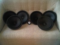
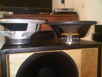
Still in preparation phase... But what a preparation it is... 😀
You know, I suffer from a disease, it's called EyeGreed or Greedy Eyes 😀
4x8 ohms and two 4 ohm speakers. 😀
And the Tang Band! I know it is a 30$ 3 inch full range with a miserable ~50-60 mm membrane, but it made my jaw drop with it's scene and good dispersion. I have never owned a full range of any kind (except for one pair of garage grade) and the sound is very satisfactory to me. I am after the imaging mainly.
Now we wait for me to construct speakers of some sort.
Best regards to all!
Attachments
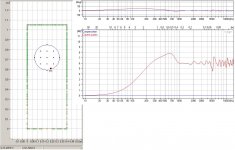
Here are the actual measurements of 11 12 inch VKN's.
From E1 through E5 1 to 4 hdve served in bass reflex and 50l sealed two by two, E5 is a never used 4 ohm which have been kept poorly in an industrial warehouse.
T1 to T6 are brand new, onlt T1 has some break in of about 2 hours without enclosure with bass ckrancked up.
15 years difference in age between the newest and the oldest one. At least 3-4 different series.
I am glad with the results, the engineers who took the measurements (manual data aquisition) said that the data is above the minimum satisfactory level.
What is on my mind is either about 125L enclosure with damped bass reflex port with diameter of 160 and lenght 260mm (~20ms group delays before applying aperiodic damping) or 140-160L aperiodic enclosure.
T2, T3 and T5 seem a good match to me?
I'm not very keen in the enclosures and due to lack of experience I can't make a decision between a 20 ms GD enclosure with steep roll off that goes little deeper and a 10-12ms GD enclosure with more gentle roll of that has ~ 34 hz @ - 5 or -6 db.
Will be glad to hear your opinions and recomendations.
p.s. have in mind that I am going to use a BSC (or a sort of... as described here: http://www.diyaudio.com/forums/full-range/180491-l-here-l-there-l-everywhere.html) to kill some 4 to 6 db from the bass driver, so the - 3 db point as well as all points of the roll of are expected to be raised to some extent with some db.
Best regards!
Attachments

Last edited:
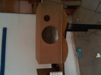
Sorry for the blog like thread, but we're advancing.
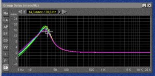
~128L enclosure with 100mm X 68-69mm vent tuned to about 30-32 hz - this gives ~16ms group delay. I have no clue whether 16ms is good or bad as those are our (for me and my friend Emil) first bass reflex design. We just follow all known steps.
This enclosure will be for a matching pair of the Ex drivers and eventually will be used to break in my drivers (the Tx drivers).
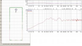
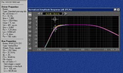
Here are some pictures of the build and a simulation of the response.
In the simulation screenshot it is seen that three of the lines for three of the E drivers overlap pretty nicely... which was a big and pleasant surprise for us!
The top line is a simulation of optimum enclosure using average data from all 8 ohm E drivers and the three lines one over another are with this enclosure and every driver's specific parameters. The fourth line is between the top and other three and is of the most different E driver.
The enclosure will have only two braces above and under the bass driver. The material is 30mm MDF for all sides top and bottom and 20mm MDF for the braces.
The stuffing is some kind of either stone or glass watting/insulation (don't know the correct term) on the sides - most thick behind the bass driver. Above it is some sort of syntepon cloth material.
I have one question:
- How about laying a very thin layer of the syntepon (syntetic as the one found in pillows) cloth on the inside of every bracing?
Any recommendations are wellcome.
I'm little affraid and concerned of the green stone/glass stuff we placed on the sides...
Interestingly the Tx drivers showed capability of reproducing low frequencies with -6 db point at ~27 hz, but in bigger enclosures. That is before break in.
I have one more question:
- How does the breaking in affect the T/S parameters? Does VAS get lower or bigger and does QTS get lower or bigger? Any other input is welcome. For Fs I know that it drops a few hz down.
+ A sub question, having in mind the data from the measurements, is it correct to expect that the T drivers will look more like the E drivers after breaking in? Or they will go in different direction? - I ask because the boxes required by the current parameters of the T drivers are little too big for me. And I don't know whether it would be possible to achieve the needed enclosure elasticity as of 200-300L box with say a 140L aperiodic enclosure.
++ And second sub question, Can Aperiodic enclosure be combined with bass reflex? I think that probably no, because it can simply mimic very low QL bass reflex box.. I don't know? 😕
+++ And... is it that bad? I mean the "slight" differences between drivers. Never mind the 4 ohm ones. The simulations show encouraging results despute the T/S parameters that are all over the place... (I need only one pair of T drivers, and IMHO about three of the T's can be used as a pair with tolerable differences)
I will have the T drivers measured once again after some hours of break in.
Best regards to all and thanks in advance for the replies!
~128L enclosure with 100mm X 68-69mm vent tuned to about 30-32 hz - this gives ~16ms group delay. I have no clue whether 16ms is good or bad as those are our (for me and my friend Emil) first bass reflex design. We just follow all known steps.
This enclosure will be for a matching pair of the Ex drivers and eventually will be used to break in my drivers (the Tx drivers).
Here are some pictures of the build and a simulation of the response.
In the simulation screenshot it is seen that three of the lines for three of the E drivers overlap pretty nicely... which was a big and pleasant surprise for us!
The top line is a simulation of optimum enclosure using average data from all 8 ohm E drivers and the three lines one over another are with this enclosure and every driver's specific parameters. The fourth line is between the top and other three and is of the most different E driver.
The enclosure will have only two braces above and under the bass driver. The material is 30mm MDF for all sides top and bottom and 20mm MDF for the braces.
The stuffing is some kind of either stone or glass watting/insulation (don't know the correct term) on the sides - most thick behind the bass driver. Above it is some sort of syntepon cloth material.
I have one question:
- How about laying a very thin layer of the syntepon (syntetic as the one found in pillows) cloth on the inside of every bracing?
Any recommendations are wellcome.
I'm little affraid and concerned of the green stone/glass stuff we placed on the sides...
Interestingly the Tx drivers showed capability of reproducing low frequencies with -6 db point at ~27 hz, but in bigger enclosures. That is before break in.
I have one more question:
- How does the breaking in affect the T/S parameters? Does VAS get lower or bigger and does QTS get lower or bigger? Any other input is welcome. For Fs I know that it drops a few hz down.
+ A sub question, having in mind the data from the measurements, is it correct to expect that the T drivers will look more like the E drivers after breaking in? Or they will go in different direction? - I ask because the boxes required by the current parameters of the T drivers are little too big for me. And I don't know whether it would be possible to achieve the needed enclosure elasticity as of 200-300L box with say a 140L aperiodic enclosure.
++ And second sub question, Can Aperiodic enclosure be combined with bass reflex? I think that probably no, because it can simply mimic very low QL bass reflex box.. I don't know? 😕
+++ And... is it that bad? I mean the "slight" differences between drivers. Never mind the 4 ohm ones. The simulations show encouraging results despute the T/S parameters that are all over the place... (I need only one pair of T drivers, and IMHO about three of the T's can be used as a pair with tolerable differences)
I will have the T drivers measured once again after some hours of break in.
Best regards to all and thanks in advance for the replies!
Attachments

Last edited:
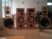
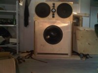
Allright, now my friend has finished speakers and I don't have any 😱 (anyway I was waiting for the transformers of the continuously variable BSC to be made)
Here are his finished speakers. Pictures of the BSC transformers you will find in this reply of this thread http://www.diyaudio.com/forums/full-range/180491-l-here-l-there-l-everywhere-2.html#post2539541
I am still thinking about the enclosure. Not that his don't sound superb, but I don't want a bass reflex, I want a TL or an aperiodic enclosure...
Best regards to all! And we're advancing! 🙂
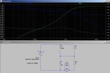
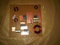
I apply a photo of the crossover - my design of the topology, electrical values taken from an 1981 DIY project for the same speakers as used published in a local magazine.
Edit: oops, sorry, just for the protocol, 38 cm (15 in) by 100 cm (39.4 in) front panel, 127L, BR d100 mm X 69 mm crossover frequencies 600-800 and 4000 Hz, orders: all second except for the ribbon HF driver which has third order.
Here are his finished speakers. Pictures of the BSC transformers you will find in this reply of this thread http://www.diyaudio.com/forums/full-range/180491-l-here-l-there-l-everywhere-2.html#post2539541
I am still thinking about the enclosure. Not that his don't sound superb, but I don't want a bass reflex, I want a TL or an aperiodic enclosure...
Best regards to all! And we're advancing! 🙂
I apply a photo of the crossover - my design of the topology, electrical values taken from an 1981 DIY project for the same speakers as used published in a local magazine.
Edit: oops, sorry, just for the protocol, 38 cm (15 in) by 100 cm (39.4 in) front panel, 127L, BR d100 mm X 69 mm crossover frequencies 600-800 and 4000 Hz, orders: all second except for the ribbon HF driver which has third order.
Attachments
Last edited:
I am advancing and tomorrow I will construct a test crossover.
I have some reaaly embarrassing questions though 😱
About coils in and out connections. Which should be to + and which to the driver?
The question is whether + is fed to the most inner winding of the coil or vice versa? I tend to think it should be fed to the most inner winding.
But there is a complication... I have a variable BSC with transformer in the bass circuit only and to make things worse it is a series crossover. 😕
I can tell which is the most inner winding of the transformer, but look where is the transformer in the circuits above. - on the other side of the bass driver 😕
I tend to think that if + is fed through the first inductance (top of the schematics), it should enter it through the inner winding, exit through the outer, enter the bass and then exit through the inner winding of the transformer.
See schematics of the crossover in post №3 here: http://www.diyaudio.com/forums/multi-way/179055-sealed-volume-2x12-tb.html#post2486025
And additional info here: http://www.diyaudio.com/forums/full-range/180491-l-here-l-there-l-everywhere.html#post2513985
Don't mind the source + and - on the schematics. Tt would be the opposite.
And... I know it is alternating current and not DC, but I had quite hard time until I got right the in/out of the inductances of my H-frames...
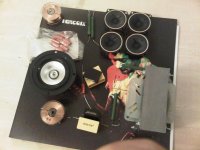
Here is a nice photo just for eye pleasure.
The four smallish speakers are a tweeters, rather good ones for 3$ each, they will be used for dipole high frequencies and other experiments.
I have some reaaly embarrassing questions though 😱
About coils in and out connections. Which should be to + and which to the driver?
The question is whether + is fed to the most inner winding of the coil or vice versa? I tend to think it should be fed to the most inner winding.
But there is a complication... I have a variable BSC with transformer in the bass circuit only and to make things worse it is a series crossover. 😕
I can tell which is the most inner winding of the transformer, but look where is the transformer in the circuits above. - on the other side of the bass driver 😕
I tend to think that if + is fed through the first inductance (top of the schematics), it should enter it through the inner winding, exit through the outer, enter the bass and then exit through the inner winding of the transformer.
See schematics of the crossover in post №3 here: http://www.diyaudio.com/forums/multi-way/179055-sealed-volume-2x12-tb.html#post2486025
And additional info here: http://www.diyaudio.com/forums/full-range/180491-l-here-l-there-l-everywhere.html#post2513985
Don't mind the source + and - on the schematics. Tt would be the opposite.
And... I know it is alternating current and not DC, but I had quite hard time until I got right the in/out of the inductances of my H-frames...
Here is a nice photo just for eye pleasure.
The four smallish speakers are a tweeters, rather good ones for 3$ each, they will be used for dipole high frequencies and other experiments.
Attachments
Last edited:
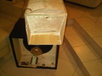
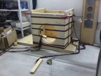
Alright, I totally screwed it up this time. While I didn't have time to prepare for building during Easter holidays, I was not able to resist a piece of plywood. I had to hear mine woofers in some kind of enclosure.
This thing that I constructed was initially planned as the chamber of an enclosure that is something like a transmission line, but expanding and serving only for membrane loading/acoustic suspension, lowering resonance and etc. - it was a long time ago, but now I felt like experimenting only with the chamber part of it.
It wasn't that bad, it even turned out that this is a good recipe for really punchy mid bass and pretty solid midrange, but that is not what I actually hoped for.
Under certain circumstances I was surprised to find out how do they actually reproduce bass at some disco clubs - by actually not letting low bass notes being reproduced. I got the same wooden punchy bam-bam lacking the so joyful low-lows...
I got a very joyful reproduction of solo drums, very live like and enthusiastic.
All this with heavily stuffed box - about 15-20 cm over the openings - outer layer is acryl wadding and inner layer is sheep wool - allot from both. Even though the wadding was so much, there was more bass through the openings than through the speaker, there was allot of midrange too.
- So anyone (such as me) who has hoped that 15-20 cm of heavy wadding on the port could do it for killing the sound of the back of the membrane and letting only air in and out - stop hoping! The glass or stone wadding on the aperiodic ports isn't there by accident... obviously...
Anything else? Although it seems I will not be able to avoid a seriously big enclosure, it was pretty entertaining experience this experiment...
What is on my mind next is using my Cerwin Vega E712 boxes as a test mules for aperiodic enclosures. I will only have to carefully remove the original bass reflex pipes, which luckily are 2X110mm per box for that model and experiment with better and properer aperiodic ports. They are something around 90-98L, so perfectly on spot as dimensions.
By the way my friend's project with the 127 L bass reflex is a total sonic success. But I am searching something more than entering driver parameters in Bass Box Pro and clicking on the "optimum" button 🙂
Still no clue for enclosure design for Aperiodic for these drivers.
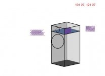
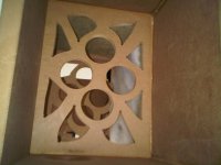
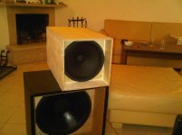
Here are some photos of the experiment.
- three overall photos;
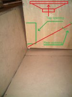
- one close up of positioning near floor and boundary with green text and green and red markings - that's how I got the closes approximation of something like low but still punchy and rather mid bass;
- one drawing of something like a design I once thought about, openings are between green lines, red lines represent the part which I constructed today;
Best regards to all!
This thing that I constructed was initially planned as the chamber of an enclosure that is something like a transmission line, but expanding and serving only for membrane loading/acoustic suspension, lowering resonance and etc. - it was a long time ago, but now I felt like experimenting only with the chamber part of it.
It wasn't that bad, it even turned out that this is a good recipe for really punchy mid bass and pretty solid midrange, but that is not what I actually hoped for.
Under certain circumstances I was surprised to find out how do they actually reproduce bass at some disco clubs - by actually not letting low bass notes being reproduced. I got the same wooden punchy bam-bam lacking the so joyful low-lows...
I got a very joyful reproduction of solo drums, very live like and enthusiastic.
All this with heavily stuffed box - about 15-20 cm over the openings - outer layer is acryl wadding and inner layer is sheep wool - allot from both. Even though the wadding was so much, there was more bass through the openings than through the speaker, there was allot of midrange too.
- So anyone (such as me) who has hoped that 15-20 cm of heavy wadding on the port could do it for killing the sound of the back of the membrane and letting only air in and out - stop hoping! The glass or stone wadding on the aperiodic ports isn't there by accident... obviously...
Anything else?
Although it seems I will not be able to avoid a seriously big enclosure, it was pretty entertaining experience this experiment...What is on my mind next is using my Cerwin Vega E712 boxes as a test mules for aperiodic enclosures. I will only have to carefully remove the original bass reflex pipes, which luckily are 2X110mm per box for that model and experiment with better and properer aperiodic ports. They are something around 90-98L, so perfectly on spot as dimensions.
By the way my friend's project with the 127 L bass reflex is a total sonic success. But I am searching something more than entering driver parameters in Bass Box Pro and clicking on the "optimum" button 🙂
Still no clue for enclosure design for Aperiodic for these drivers.
Here are some photos of the experiment.
- three overall photos;
- one close up of positioning near floor and boundary with green text and green and red markings - that's how I got the closes approximation of something like low but still punchy and rather mid bass;
- one drawing of something like a design I once thought about, openings are between green lines, red lines represent the part which I constructed today;
Best regards to all!
Attachments


Last edited:
Testing continues, or maybe I should call it research and development? 😱
I made a test enclosure for the TB, adjusted the crossover a bit, used some boost through an equalizer (20hz +8, 40hz +6 and 63hz+5-6 db), also I set the loading of the secondary winding to what is 6-8 db depth of correction according to the simulations.
And voala - design has green light for further development.
I never knew voices, drums and guitars can be so well articulated and clear.
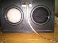
After I proved that aperiodic enclosures can satisfy my demands and that they have enough advantages, I moved on and installed the two 4 ohm VKN's into my E-712's - the direct fit and 1:1 matching bolt patterns were a surprise.
Original crossover seems to work fine as the WOOFHsomething is also 4 ohm.
First step was to increase the wadding to 2/3rd's of the internal volume, I used foam, polyester wadding and long hair sheep wool wadding. The surprise came when I found out that this way the speakers became more bass heavy than with original woofers.
Now I'm experimenting with the ports. And also I consider buying a variovent or another commercially available aperiodic port and dissecting it.
From what I have read the combination of elasticity of the enclosed air and resistance of the port must be such that the driver resonance does not change and the impedance peak at driver Fs must be lowered.
Elasticity (compliance) of suspension must be matched by port conductivity added to air elasticity. Impedance peak must be reduced by port resistance.
There are equations, but even if I get all variables and result right, I can’t interpret the result into port resistance/conductivity.
So I came to conclusion that port adjustments must be made parallel to measurements of speaker impedance. There must be only one impedance peak, it should be lower than the free air peak and it should be at the same frequency as free air.
Laid down like that it seems that the task is not so impossible, even it becomes within reach of the ordinary hobby man.
Question:
Is this a valid statement:
Aperiodic enclosure can be identified by it's single impedance peak, that is lower than driver's free air one and occurring at the same frequency.
If this is so, I just found out the method for designing aperiodic enclosures at home.
Some photos follow.
Best Regards to all!
I made a test enclosure for the TB, adjusted the crossover a bit, used some boost through an equalizer (20hz +8, 40hz +6 and 63hz+5-6 db), also I set the loading of the secondary winding to what is 6-8 db depth of correction according to the simulations.
And voala - design has green light for further development.
I never knew voices, drums and guitars can be so well articulated and clear.
After I proved that aperiodic enclosures can satisfy my demands and that they have enough advantages, I moved on and installed the two 4 ohm VKN's into my E-712's - the direct fit and 1:1 matching bolt patterns were a surprise.
Original crossover seems to work fine as the WOOFHsomething is also 4 ohm.
First step was to increase the wadding to 2/3rd's of the internal volume, I used foam, polyester wadding and long hair sheep wool wadding. The surprise came when I found out that this way the speakers became more bass heavy than with original woofers.
Now I'm experimenting with the ports. And also I consider buying a variovent or another commercially available aperiodic port and dissecting it.
From what I have read the combination of elasticity of the enclosed air and resistance of the port must be such that the driver resonance does not change and the impedance peak at driver Fs must be lowered.
Elasticity (compliance) of suspension must be matched by port conductivity added to air elasticity. Impedance peak must be reduced by port resistance.
There are equations, but even if I get all variables and result right, I can’t interpret the result into port resistance/conductivity.
So I came to conclusion that port adjustments must be made parallel to measurements of speaker impedance. There must be only one impedance peak, it should be lower than the free air peak and it should be at the same frequency as free air.
Laid down like that it seems that the task is not so impossible, even it becomes within reach of the ordinary hobby man.
Question:
Is this a valid statement:
Aperiodic enclosure can be identified by it's single impedance peak, that is lower than driver's free air one and occurring at the same frequency.
If this is so, I just found out the method for designing aperiodic enclosures at home.
Some photos follow.
Best Regards to all!
Attachments


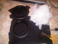
Yesterday I made the Aperiodic ports. One from wool cloth stuffed with polyester wadding and one Lycra cloth (sourced from... you know... you know what DuPont was famous for... 😉 🙂 ) stuffed with the same wadding.
The wool cloth is too air tight, the Lycra is OK.
Both types exhibit membrane like motion that must be cured with fixing metal nets.
Results are promising though.
It seems that area can be increased in order to maintain flow and to allow for more acoustic absorption with the same flow and resistance.
I don't know why I mistakenly considered those enclosures to be 90-98 L, they are actually 79L internal volume. This brings them to the small side for aperiodic enclosure for drivers with VAS of over 200 L.
40-100 hz region is definitely better reproduced compared to sealed, bass reflex and two 115x18 mm openings.
Low end is comparable to bass reflex, but it subjectively seems to me that there is better definition with aperiodic ports.
I apply two photos.
Best Regards to all!
p.s. I can't be the only one who is interested in this type of enclosure?
Attachments
Alright, I know it is childish to draw in Paint, but that is what I can do.
Finally, I came up with a design that I like, not only aesthetically, but also functionally.
All drivers for the upper part are shown here in that thread. The aim with that design is to have one sure acoustic center of the upper part.
Below there is a 15'' in a 160-220 L ported cabinet, which will have interchangeable ports, one aperiodic and one bass reflex.
The above part will be either sealed, H-frame or U frame. Either way there will be four more HF drivers on the back of the enclosure.
There is possibility the center part with the Tangband and the HF drivers to be moved forward between 6 to 15 cm for time alignment. - thus forming two separate H-frames.
Even if the upper baffle is flat, I think worst scenario is directivity anomalies, but at least it will always be pointed forward.
The dimensions of the front baffle are 122X71 cm approximately. The reason for the width is apparent and the reason for the height is that my ear when seated is at ~102-105 cm above the floor, which is where the Tangband is centered.
I will aim for crossover frequencies ~60-80 Hz, 1200-1500 Hz and ~10000 Hz all first order and whichever works well with series.
I have tested the crossovers with superb results.
I have also tested the adjustable BSC with great success.
Luckily the whole baffle step slope or the whole H or U frame resonance lies in the frequency band of the 12 inch drivers, so the adjustable BSC will be only in their circuit.
The two treble circuits might receive adjustable L-pads for luxury and pomposity: D
The 12-inch drivers and the Tangband will receive zobel circuits.
The drawing is with very accurate scale.
With that arrangement, I am after good stereo image and hopefully achieving one common acoustic center. I will be thankful for any opinion or recommendation regarding time alignment and any anomalies.
This is final design decision.
Best Regards!
Attachments

Last edited:
I am still thinking about the enclosure. Not that his don't sound superb, but I don't want a bass reflex, I want a TL or an aperiodic enclosure...
Is this a valid statement:
Aperiodic enclosure can be identified by it's single impedance peak, that is lower than driver's free air one and occurring at the same frequency.
A true aperiodic cab has a flat impedance which is defined by Fs/Qts, the otherwise ~equivalent to a T/S maximally flat vented alignment, so the lower the desired F3, the higher Qts must be for a given Fs and consequently, the higher the cab's net Vb must be according to T/S. To keep cab net Vb reasonable then requires a correspondingly low Vas to offset it.
The reality is that it will often have a minor single very low Q peak at or a bit above Fs, i.e. where a vented alignment's upper impedance peak would be if tuned to Fs.
Anyway, Rick Shultz [AKA 'exolinear'] spells it all out with the math to make your own calculator in his Alpha TL article: http://documents.jordan-usa.com/Famous-Articles/Schultz-Alpha-Transmission-Lines.pdf
GM
Thanks GM!
Recently I was thinking on aperiodic enclosures again. I have read all from Mr. Jordan on the topic, as well as anything else found on the web.
One major obstacle before the popularity of the aperiodic enclosures amongst DIY hobbyists is that the port cannot be replicated.
It was impossible for a homegrown enthusiast to replicate the ARU of Goodmans Axiom back in the 50's, so they sold it separately.
Today if someone makes a good aperiodic enclosure with popular driver it would be again very hard for anyone to replicate the result without conducting the same measurements. (mainly impedance measurements)
That is because no one has been thinking seriously on the matter for the last 50-60 years.
Back then in the Axiom times, they didn't have so much vacuum cleaners as today and even fewer were the adjustable ones.
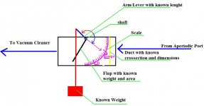
See the enclosed drawing. It represents an air flow meter.
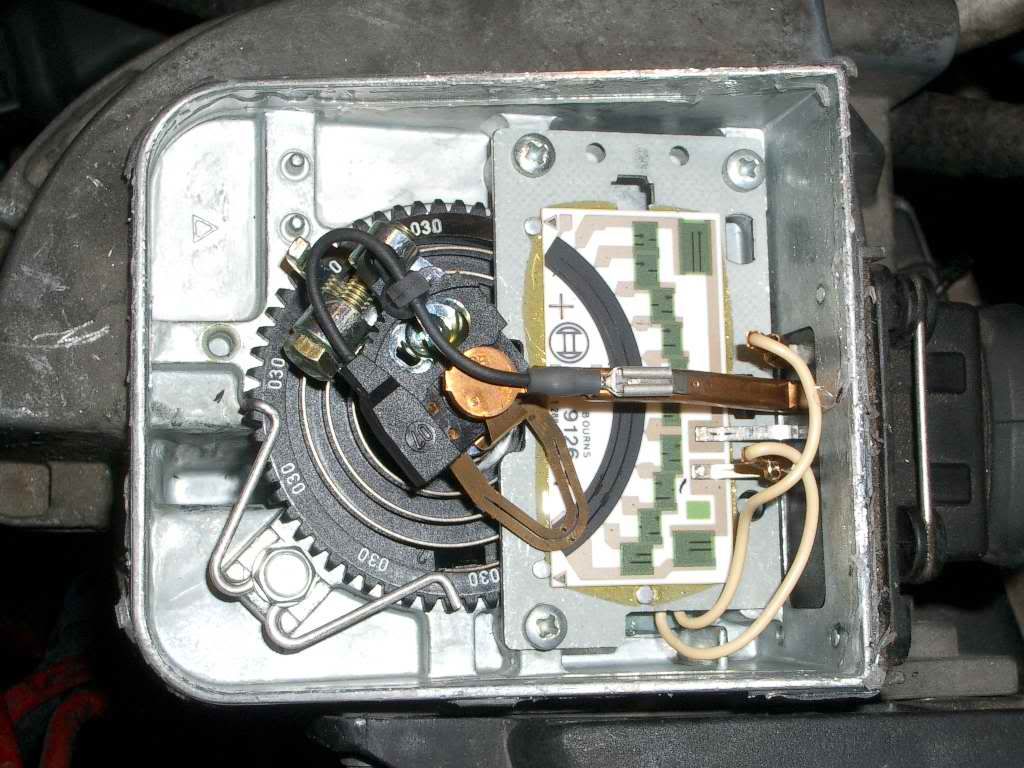

On the pictures above you can see a flap type MAF.
My proposition relies on the same principle. The author of the project just has to construct a simple device consisting of rectangular duct with known dimensions, a flap with known mass and dimensions, an axle (shaft), a lever, a pointer and a scale with known zero and target coordinates in relation to the shaft.
First the designer has to find the zero position, this is with the meter free flowing. The zero position is an abstract one, just coordinates of the pointer end with the given lever length and weight attached to it.
Then he should find pointer end coordinates with the duct intake connected to the aperiodic port.
Today almost every vacuum cleaner has adjustable power, so finding the same zero position should be quite easy through adjusting the suction power.
After the zero position has been found, it is a matter of adjusting the port until the meter reads the same as the one of the original author of the project.
I think that an average hobby-man could construct such a meter in about half an hour.
Dimensions are abstract and meaningless, you only have to replicate the original ones. The shaft and the lever can be made from hard copper wire.
The exhaust side of the meter can be closed by a piece of cardboard with a hole for the vacuum cleaner pipe. For every particular port the dimensions of the duct (meter body) can match the dimensions of the port.
What do you think? If I ever construct an aperiodic enclosure I will definitely do this in order to let other replicate the design.
Best regards!
P.S. See other enclosed photos to get an idea where the design started in that thread went 😀 A 220 L bass reflex enclosure with Dayton ST-385 and an OB designed with MJK's Mathcad on top of it. Crossover is targeted ay the 60-90 hz region. Have in mind, that this system incorporates my variable BSC mentioned above, so the OB part is actually flat from 90-100 hz on.
Some more info on my ongoing project http://penkiller.com/index.php/topic,383.0.html
Even more info in Bulgarian: http://penkiller.com/index.php/topic,276.0.html
When I finish it, I will post designing, construction and results in a separate thread.
Recently I was thinking on aperiodic enclosures again. I have read all from Mr. Jordan on the topic, as well as anything else found on the web.
One major obstacle before the popularity of the aperiodic enclosures amongst DIY hobbyists is that the port cannot be replicated.
It was impossible for a homegrown enthusiast to replicate the ARU of Goodmans Axiom back in the 50's, so they sold it separately.
Today if someone makes a good aperiodic enclosure with popular driver it would be again very hard for anyone to replicate the result without conducting the same measurements. (mainly impedance measurements)
That is because no one has been thinking seriously on the matter for the last 50-60 years.
Back then in the Axiom times, they didn't have so much vacuum cleaners as today and even fewer were the adjustable ones.
See the enclosed drawing. It represents an air flow meter.

On the pictures above you can see a flap type MAF.
My proposition relies on the same principle. The author of the project just has to construct a simple device consisting of rectangular duct with known dimensions, a flap with known mass and dimensions, an axle (shaft), a lever, a pointer and a scale with known zero and target coordinates in relation to the shaft.
First the designer has to find the zero position, this is with the meter free flowing. The zero position is an abstract one, just coordinates of the pointer end with the given lever length and weight attached to it.
Then he should find pointer end coordinates with the duct intake connected to the aperiodic port.
Today almost every vacuum cleaner has adjustable power, so finding the same zero position should be quite easy through adjusting the suction power.
After the zero position has been found, it is a matter of adjusting the port until the meter reads the same as the one of the original author of the project.
I think that an average hobby-man could construct such a meter in about half an hour.
Dimensions are abstract and meaningless, you only have to replicate the original ones. The shaft and the lever can be made from hard copper wire.
The exhaust side of the meter can be closed by a piece of cardboard with a hole for the vacuum cleaner pipe. For every particular port the dimensions of the duct (meter body) can match the dimensions of the port.
What do you think? If I ever construct an aperiodic enclosure I will definitely do this in order to let other replicate the design.
Best regards!
P.S. See other enclosed photos to get an idea where the design started in that thread went 😀 A 220 L bass reflex enclosure with Dayton ST-385 and an OB designed with MJK's Mathcad on top of it. Crossover is targeted ay the 60-90 hz region. Have in mind, that this system incorporates my variable BSC mentioned above, so the OB part is actually flat from 90-100 hz on.
Some more info on my ongoing project http://penkiller.com/index.php/topic,383.0.html
Even more info in Bulgarian: http://penkiller.com/index.php/topic,276.0.html
When I finish it, I will post designing, construction and results in a separate thread.
Attachments
Last edited:
Greets!
Interesting idea, thanks for sharing!
If one designs/builds per the TL documentation there's no need to experiment beyond trying different stuffing materials than polyfil, fiberglass insulation, but always nice to have other options, so looking forward to your MAF solution.
WRT the ARU, I didn't know such existed during my main learning years, only Olson's? click test ckt. to adjust port damping by ear until I got a scope to see the impedance change.
Like the OB, nice seeing a decent amount of piston area for the lower mids, but ideally not enough woofer area, so are you planning dual 15" or at least an 18" for the finished speakers?
GM
- Status
- Not open for further replies.
- Home
- Loudspeakers
- Multi-Way
- Sealed Volume 2x12 and a TB?