Has anyone experimented with a single sealed sub enclosure with two or more chambers connected by lengths of PVC pipe? I've seen this done with ported enclosures and a different tuning frequency for each vent, but have no idea how it will impact a sealed design.
- Driver mounted traditionally with cone contacting air, not hidden in box
- 'Front' chamber is large enough to hold the driver
- PVC pipe connects front chamber to rear chamber
- Rear chamber provides balance of required sealed enclosure air space
Basically, I'd like to do a variation on the old 'blow through' pickup truck sub install, but with the sub itself inside the cab and most of the enclosure airspace back in the bed. I have a JL 8W7 and a regular cab Ranger with bucket seats. It would be great if two or three lengths of 4" PVC pipe with threaded adapters could be run through the rear wall of the cab and the front of the bed to connect a small box in the truck with a large one in the bed, say, inside a metal toolbox.
It is not practical to build the recommended 8W7 sealed enclosure in my space constraints - shifter for T5 tranny sits much further back than stock and I have plans for the space behind each seat.
Is there a minimum cross-sectional area for the connecting tubes that I must adhere to for predictable sealed-box response? Some fraction of the sub cone area?
Tips/advice appreciated.
You're talking about the Helmholtz resonator , which is a closed chamber with a hole or a duct . Air inside the chamber resonates at a frequency depending on volume and the hole diameter . It's the basis for bass reflex boxes , and it is represented electrically as common passive elements such L , R , C which assume the behavior of air ,as it is an elastic fluid having mass ,behaving like a spring ,having resistance and some hysteresis ...
What I haven't been able to deduce (or Google) is at what point the connecting tube/s cross-sectional area becomes large enough that the resonant effects are either outside the pass band (20-85Hz) or not present at amplitudes that need to be considered. Is this sealed enclosure's airspace as it relates to T/S parameters and subwoofer performance simply a function of total internal air volume/pressure of the front box/rear box/connecting tubes?
Would the connecting tube resonance have an audible impact on the sub's performance if the tube/s are part of the enclosure's airspace and isolated from the cabin and the front of the woofer cone? I'd have no problem installing three or four 4" PVC connecting tubes between the front and rear portions of the enclosure if necessary, but obviously fewer tubes are easier to implement and more desirable.
Would the connecting tube resonance have an audible impact on the sub's performance if the tube/s are part of the enclosure's airspace and isolated from the cabin and the front of the woofer cone? I'd have no problem installing three or four 4" PVC connecting tubes between the front and rear portions of the enclosure if necessary, but obviously fewer tubes are easier to implement and more desirable.
Hi , I would save space ; instead ,lower the velocity of air ..or whatever !
Audiogear Reviews - Enclosure Design - Aperiodic Membrane
🙂
Audiogear Reviews - Enclosure Design - Aperiodic Membrane
🙂
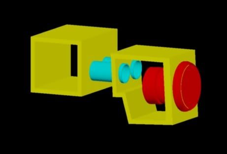
I've always wanted to try aperiodic, but think 8W7 Qts is too high, exterior elements (i.e. water) can be a problem as well. Here's a quick sketch of what I'm proposing (cabinet sides not shown for clarity):
briansz : I've always wanted to try aperiodic, but think 8W7 Qts is too high..
Hi briansz,
Aperiodic?, The proposed designs here below can near all to be characterized as aperiodic designs..
Here's a educational guess of what you could accomplish. The preliminarily T/S I've used is fs=~38Hz,Qts=~0.67 and Vas= ~9.25L but must be known in prior if any of the designs are to be trustworthy:
1.Your original suggestion of two connected closed box chambers, on ore more connecting tubes.(opt summed closed volumes = <=~80L; f3=~40Hz) or:
2.One of the connecting tubes is used as a return from the second volume: Resulting in a ~flat FR BR(opt summed main volume=~ >=44L; f3=~22Hz = min tuning) or:
3. A Quarter-wave BR(a TL design) with a ~minimum 16L chamber volume and a minimum 10L port volume;in total 26L; f3=~26 Hz)or:
4. Can be turned into a T-QWBR (Tapped-Quarter-Wave BR) if a few Liters is added to #3.
5. A DBR using 2 volumes as design #1.and 2 connecting tubes where one of the tubes is returning back and terminates into the cab free air or:
6.Can be turned into a T-TQWT(= minimum overall volume for a flat FR and BW=~110Hz if the first volume is allowed to have a volume of ~11L.
The total T-TQWT volume including the connecting tubes would be about 29L= a ~cu.ft;f3=~25Hz.
Actually the T-TQWT is derived from the proposed TL because a T-TQWT is a TL where the terminus and the driver front areas are both merging the sound outputs into a common single port.
b 🙂
PS: Why didn't you post to the Car Audio forum?
Last edited:
Why not build the whole enclosure in the bed and just cut through for the cone? I understand what you want to do-just not why you want to do it?
Won't work. Ever see a pickup driving on uneven terrain? The bed and cab move relative to one another. This is normal frame flex just as a tall steel skyscraper sways in the wind. The connecting ports will break apart as soon as you pull out of the driveway. You would have to place either the inside or the outer box on a movable mount and oversize the holes in the cab or bed and add a flexible membrane to keep out the noise and weather. Maybe some sort of flexible duct hose would work.
I wouldn't want to trash my truck to do this.
I wouldn't want to trash my truck to do this.
Not familiar with your vehicle, we don't get them in the UK-but I am aware that the cabin volume is going to be pretty similar to my Mini Cooper S.
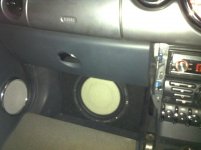
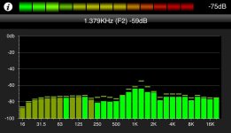
If you're going for SQ then don't worry about box volume-go for something that'll just fit around the sub: cabin gain is your friend and a "linkwitz transform" EQ without any electronics. I found my cabin gain mapped out on DIYMA and used it when designing my enclosue, which is 0.126cf for a 10". Fb is 76Hz, F3 is 74Hz and sub plays flat down to 30Hz with zero EQ, and I can dial in more bass easily if wanted/needed. The RTA shot shows my system response from drivers seat with the sub in the passenger footwell-NO EQ at all, gains set by ear and at this point arbitary crossover points and no tuning time🙂
If you're going for SQ then don't worry about box volume-go for something that'll just fit around the sub: cabin gain is your friend and a "linkwitz transform" EQ without any electronics. I found my cabin gain mapped out on DIYMA and used it when designing my enclosue, which is 0.126cf for a 10". Fb is 76Hz, F3 is 74Hz and sub plays flat down to 30Hz with zero EQ, and I can dial in more bass easily if wanted/needed. The RTA shot shows my system response from drivers seat with the sub in the passenger footwell-NO EQ at all, gains set by ear and at this point arbitary crossover points and no tuning time🙂
Attachments
Last edited:
I'm aware that substantial soft gasket material will be required around the tubes for flex between the cab and bed. At this point, the truck is 28 years old and will never be worth less than it currently is unless somebody hits it. It's a $500 vehicle with a $5000 motor in it <lol>. It is a 2WD, so that will help the flex issue a bit, I'm not rock crawling with it. This is my project truck that ended up my daily driver thanks to a hit and run last year that totaled my car.
Gen I Rangers are very plentiful in junkyards and I have a battery-powered sawzall and a Mig welder if I ever change my mind, metal to 'undo' the modification is worth about $10. I'm not afraid of cutting/welding...........
😉
To answer the earlier question, I posted here in this category since a perusal of Car Audio fetched mostly threads on amp repair. Thank you for all the info on enclosure types.
Baron, you bring up a good point. I could stop being lazy and measure the transfer function of the truck and see what F3 really needs to be. I've mostly grown up and this is a SQ system. 3-Way MB Quart QM-series components, 2x Sony XM-7547 amps at 100x4 (two channels of one amp bridged to give the sub ~ 400x1). I have a Clarion 3-way crossover that has variable boost/center freq/Q to do active high pass and an Audio Control DQL if more massaging is needed.
Sounds easier than cutting 🙂
Sounds easier than cutting 🙂
Is it possible.. I'm curious how large would the back chamber volume be, how long would the tubes be and what diameter, and what would the front chamber volume be, I would like to model this. for fun 🙂
As it's shown, the front chamber is nominally .375 cubic feet, rear .5 cubic feet, vents are two 3" ID at 5" long.
I've mostly grown up and this is a SQ system.
The difference between a man and a boy is the size of their toys 😀
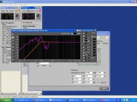
Check the graph below, there's an F350 in the mix-which may be close enough to your vehicle that it doesn't matter.
http://farm4.static.flickr.com/3194/2516534482_b0d155d5ac_o.jpg
I've read quite a lot on the topic, Patrick Bateman has a very interesting theory regarding it-seems to make sense. Basically cabin gain is pressure and standing waves, the internal dimensions of your vehicle can give you clues to where you'll get the peaks: height of cab, width of cab and length of cab. If you ever venture onto DIYMA extremerevoltion can model it for you, otherwise if you know someone with LEAP it can model it.
Does Anyone Understand Cabin Gain - DIYMA.com - Scientific Car Audio - Truth in Sound Quality
I've actually been on DIYMA for awhile, but folks there suggested diyaudio for my question about the multi-chambered box. Didn't realize you could calculate cabin gain from dimensions; I was just thinking of the old-fashioned way with PC-based RTA software and a measurement mic (meter sub in car, meter sub in free space, difference = cabin gain). I've also got an old Gold-Line 30 RTA, but the PC's easier to use when comparing curves. Love Patrick Bateman's threads, have killed many hours reading the horn ones, but did not realize he had explored cabin gain.
I guess if I had to, I could pick up one of the new Type R 8's or even use my old JL 10W6v1, but I got the 8W7 in original box for a great price and want to try and use it. I'll have to do some cutting and fab together a test box for experimentation. Supposed to get a big dump of snow here tonight and tomorrow so it may have to wait a few days.
I guess if I had to, I could pick up one of the new Type R 8's or even use my old JL 10W6v1, but I got the 8W7 in original box for a great price and want to try and use it. I'll have to do some cutting and fab together a test box for experimentation. Supposed to get a big dump of snow here tonight and tomorrow so it may have to wait a few days.
Yes, dimensions will do it, but if you've a sub and RTA it's probably quicker and more accurate-provided the test sub is going where you're going to fit your W8 and you mic from your head position.
Yup, Patricks threads are great-have you visited Audio Psychosis?-it's his own forum-he's the main contributer-there's some interesting stuff on there too.
What's your username on diyma?
I'm gonna pull the specs off the w8 and see how it'd model in my car-will post the graphs🙂
Yup, Patricks threads are great-have you visited Audio Psychosis?-it's his own forum-he's the main contributer-there's some interesting stuff on there too.
What's your username on diyma?
I'm gonna pull the specs off the w8 and see how it'd model in my car-will post the graphs🙂

The ports would tune to 100.6Hz back, 116.3Hz front, as long as the XO is set below ~80Hz with a high order XO the two chambers will couple effectively.
Thanks everybody for the good info!
- I think I'm going to try out what Baron has suggested first; if it doesn't work out, I can always use that box as the front chamber of the two-box-and-tubes design and go from there.
- 8W7 isn't too useful above 85Hz to begin with; Clarion MCD360 crossover is 18dB/Octave slope so it might actually work with the twin-chamber design if the tiny box/cabin gain method is not satisfactory.
- I've got the same ID on DIYMA as here (original, huh?)
- Snow-Pocalypse seems to have happened (a foot and counting overnight), so I doubt I'll be cutting any MDF until at least next weekend.
- Status
- Not open for further replies.
- Home
- Loudspeakers
- Subwoofers
- Sealed enclosure, multiple connected chambers?