Hi folks,
Recent weeks, I checked and stressed out all diyaudio forum and other audio websites to find a schematics similar to AN, but with 6N6P tube.
Don't expect from me to design one because, I don't know how to do that 🙂 but I can put circuit all together without problem.
Reason that I want to use other tube than 6SN7 is many schematics are online, very easy to find and I want to try something else.
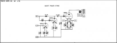
I attach schematics from AN, model called Quest and I'm wondering how 6N6P tube can fit in that circuit with necessity adoption. Of course, two triodes require decoupling capacitor among them.
Unless this cannot be done, I'm open to suggestions and whatever help I can get to make this amp 😛
Thanks
sefa
Recent weeks, I checked and stressed out all diyaudio forum and other audio websites to find a schematics similar to AN, but with 6N6P tube.
Don't expect from me to design one because, I don't know how to do that 🙂 but I can put circuit all together without problem.
Reason that I want to use other tube than 6SN7 is many schematics are online, very easy to find and I want to try something else.
I attach schematics from AN, model called Quest and I'm wondering how 6N6P tube can fit in that circuit with necessity adoption. Of course, two triodes require decoupling capacitor among them.
Unless this cannot be done, I'm open to suggestions and whatever help I can get to make this amp 😛
Thanks
sefa
Attachments
Here's the link to a 6N6-300B design that looks very good. I have learned a good bit from reading through the posts in this thread.
http://www.diyaudio.com/forums/tubes-valves/218217-deathtrap400-pretty-damn-good-300b-amp.html
http://www.diyaudio.com/forums/tubes-valves/218217-deathtrap400-pretty-damn-good-300b-amp.html
Thanks.
Actually that thread I read it all over and designer made the circuit excellent and offering modules. I check his website where he offers variety of modules and looks great designed and build. Beside the modules with chip amp, tube amp as it called - DG 300B, I didn't see much builds by the builders.
Anyway, if I want to build his design and try it, eventually like it 🙂 I have some concerns on his designs - please bear me as I do not understand precisely tube topologies: there is negative voltage (-225V) supplied on the half tube of the 6N6P - usually when other tubes are used with 300B, there isn't any negative voltage. Another concern is, there isn't any Cathode resistor. I can say, almost all circuits I seen have resistor attached on the cathode.
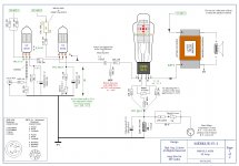
Searching for ideas on how to implement 6N6P tube, I came across this schematics where 6H30 tube is applied with 300B tube.
Will this schematics work with 6N6P just to modify the Rk and adding capacitor 0.1 uF in series with R6 resistor?
Will this schematics work with 6N6P just to modify the Rk and adding capacitor 0.1 uF in series with R6 resistor?
Attachments
Last edited:
I've used the Russian 6N6P in my phono pre and line stage ( both fully differential designs ) and have not been too impressed with it. At my OP (25mA/sec@150V) they don't last. While the 6N30 has lower mu, it will last 4X as long and sound much better. Also, at my OP the grid bias voltage is double that of the 6N6P (-6V to -7V vs. ~-3V), so more dynamic headroom. Downside? 4X the cost! BTW I have a bunch of matched section 6N6Ps that I'd part with for cheap.
Searching for ideas on how to implement 6N6P tube, I came across this schematics where 6H30 tube is applied with 300B tube.
Will this schematics work with 6N6P just to modify the Rk and adding capacitor 0.1 uF in series with R6 resistor?
Yes, it will work.
Attachments
Hi folks,
Recent weeks, I checked and stressed out all diyaudio forum and other audio websites to find a schematics similar to AN, but with 6N6P tube.
Don't expect from me to design one because, I don't know how to do that 🙂 but I can put circuit all together without problem.
Reason that I want to use other tube than 6SN7 is many schematics are online, very easy to find and I want to try something else.
I attach schematics from AN, model called Quest and I'm wondering how 6N6P tube can fit in that circuit with necessity adoption. Of course, two triodes require decoupling capacitor among them.
Unless this cannot be done, I'm open to suggestions and whatever help I can get to make this amp 😛
Thanks
sefa
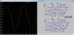
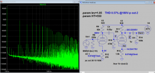
It will work without modification with 6n6 in place of 6sn7. In the sim you can see quite a bit of distortion as is, without connecting to 300b, with even harmonic dominance esp. at higher level, making it more pleasant.
Attachments
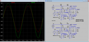
Here is my latest sim. 180V-p @<0.6% distortion, see that is any help.
Attachments
Last edited:
🙂
Koonw,
I appreciate you're doing measurements for me and interested guys on question on, 6N6P tube driver for the 300B. 🙂
My raw power supply voltage is around 430 VDC, and regulated is 360 - 380 VDC. I have output transformers Ra=3.5 k and 2.5 k for the 300B, each handling 200 mA if I want to use PSE.
Can you please, add measurements with 360 - 380 VDC voltage for the 6N6P?
As bekim pointed out on coupling capacitor among half tubes - V1 and V2, should a capacitor be in that place for this tube? Reason I'm asking is that, almost all circuits when 6N6P tube is involved, I've seen a capacitor between tube halves.
BTW, I like your simulation software 🙂 What application you use?
Appreciate all feedback as always.
Here is my latest sim. 180V-p @<0.6% distortion, see that is any help.
Koonw,
I appreciate you're doing measurements for me and interested guys on question on, 6N6P tube driver for the 300B. 🙂
My raw power supply voltage is around 430 VDC, and regulated is 360 - 380 VDC. I have output transformers Ra=3.5 k and 2.5 k for the 300B, each handling 200 mA if I want to use PSE.
Can you please, add measurements with 360 - 380 VDC voltage for the 6N6P?
As bekim pointed out on coupling capacitor among half tubes - V1 and V2, should a capacitor be in that place for this tube? Reason I'm asking is that, almost all circuits when 6N6P tube is involved, I've seen a capacitor between tube halves.
BTW, I like your simulation software 🙂 What application you use?
Appreciate all feedback as always.
🙂
Koonw,
I appreciate you're doing measurements for me and interested guys on question on, 6N6P tube driver for the 300B. 🙂
My raw power supply voltage is around 430 VDC, and regulated is 360 - 380 VDC. I have output transformers Ra=3.5 k and 2.5 k for the 300B, each handling 200 mA if I want to use PSE.
Can you please, add measurements with 360 - 380 VDC voltage for the 6N6P?
As bekim pointed out on coupling capacitor among half tubes - V1 and V2, should a capacitor be in that place for this tube? Reason I'm asking is that, almost all circuits when 6N6P tube is involved, I've seen a capacitor between tube halves.
BTW, I like your simulation software 🙂 What application you use?
Appreciate all feedback as always.
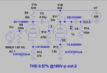
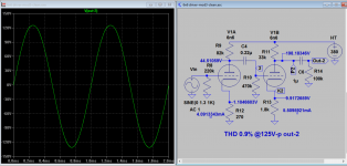
I just drop HT to 380V you requested, the output level is still very reasonable without modification, apart distortion increased a bit to 0.9% @125V-p. I am not sure about drive level for 300b you have, assumed bias at 70V, this is more enough. If direct coupled without a capacitor between V1A and V1B, your output voltage will be limited to < 80V-p as you will lose some HT voltage in the cathode, and distortion is harder to control. I think it can drive your 300b with either OT to full power.
Edit: I use LTSpice, Google it you can find Linear Technology to download a free copy and many tube models from our Diyaudio forum.
Attachments
Last edited:
That's great Koonw.
Do you think is better to not use coupled capacitor among the V1A and V1B for higher output? Because, if I can drive 300B with less Vin that will be great.
Using your design provided, would you specify what rating on resistors should I use, let's say R9 and R11 maybe 3W..?
Thanks
Do you think is better to not use coupled capacitor among the V1A and V1B for higher output? Because, if I can drive 300B with less Vin that will be great.
Using your design provided, would you specify what rating on resistors should I use, let's say R9 and R11 maybe 3W..?
Thanks
That's great Koonw.
Do you think is better to not use coupled capacitor among the V1A and V1B for higher output? Because, if I can drive 300B with less Vin that will be great.
Using your design provided, would you specify what rating on resistors should I use, let's say R9 and R11 maybe 3W..?
Thanks
Yes, you should use capacitor coupling if the HT is limited. The power Watts=I*I*R or V*I. E.g Current in R11 33K is 5.5mA, so W=5.5*5.5*33=0.998, or voltage across the resistor times current, (380-198)*0.0055~=1W. 3W is very good choice.
🙂
Koonw, I appreciate all the work you did for me and interested folks.
Next coming days I will try the circuit with all parts as you provided and will check how works altogether.
If the circuit works well with one 300B tube, I can try with two tubes - PSE, hopefully I would like the sound of it 🙂
As you asked on the bias for the 300B tubes, I purchased matched pair 72 mA EH gold grid and I have try them on another amp and they sound good.
Thanks 🙂
Yes, you should use capacitor coupling if the HT is limited. The power Watts=I*I*R or V*I. E.g Current in R11 33K is 5.5mA, so W=5.5*5.5*33=0.998, or voltage across the resistor times current, (380-198)*0.0055~=1W. 3W is very good choice.
Koonw, I appreciate all the work you did for me and interested folks.
Next coming days I will try the circuit with all parts as you provided and will check how works altogether.
If the circuit works well with one 300B tube, I can try with two tubes - PSE, hopefully I would like the sound of it 🙂
As you asked on the bias for the 300B tubes, I purchased matched pair 72 mA EH gold grid and I have try them on another amp and they sound good.
Thanks 🙂
I just drop HT to 380V you requested, the output level is still very reasonable without modification, apart distortion increased a bit to 0.9% @125V-p. I am not sure about drive level for 300b you have, assumed bias at 70V, this is more enough. If direct coupled without a capacitor between V1A and V1B, your output voltage will be limited to < 80V-p as you will lose some HT voltage in the cathode, and distortion is harder to control. I think it can drive your 300b with either OT to full power.
Edit: I use LTSpice, Google it you can find Linear Technology to download a free copy and many tube models from our Diyaudio forum.
This circuit with 6N6P tube looks promising. I will try myself as well. 🙂
Koonw,
What Vin you try with this simulation circuit to achieve the graph and which is max Vin before clipping?
Thank you for sharing.
bekim
This circuit with 6N6P tube looks promising. I will try myself as well. 🙂
Koonw,
What Vin you try with this simulation circuit to achieve the graph and which is max Vin before clipping?
Thank you for sharing.
bekim
Hi, Vin is 1.3 V-p, just like the graph shown it's almost clipping. Good luck!
Koonw,
I try yesterday (as I was awaiting the transformer to arrive) your design and seems to work. But, there is a 60Hz.
As I told you before, I have regulated power supply and same works great with another setup @380VDC where no hum at all can be heard on other setups such; 6SN7 + 300B and 6N1P-EV + KT88.
I was able to trace with my old analog scope the noise and, its obvious that it's coming from the output of the 6N6P - even without connecting the 300B. I have many, new 6N6P tubes and I swap them, but same.
When the amp it's playing for some minutes @ moderate level, can say 2-4 Watts, hum it's not noticeable, but again when no signal, can be heard again on the speaker.
Thanks
sefa
Last edited:
Koonw,
I try yesterday (as I was awaiting the transformer to arrive) your design and seems to work. But, there is a 60Hz.
As I told you before, I have regulated power supply and same works great with another setup @380VDC where no hum at all can be heard on other setups such; 6SN7 + 300B and 6N1P-EV + KT88.
I was able to trace with my old analog scope the noise and, its obvious that it's coming from the output of the 6N6P - even without connecting the 300B. I have many, new 6N6P tubes and I swap them, but same.
When the amp it's playing for some minutes @ moderate level, can say 2-4 Watts, hum it's not noticeable, but again when no signal, can be heard again on the speaker.
Thanks
sefa
60hz sounds like mains hum to me (not from PSU), you maybe have a ground loop problem. Do you connect chassis to PE (Physical Earth)? What about the input side, it's connected to PE? That maybe also the cause of ground loop. This circuit has very high gain, so care to be taken to reduce the hum picked up or due to ground loop. You can short the input to test if the hum still there. The triangular shape ground in sch refers to signal ground. You can try to connect a 1 ohm resistor from the signal ground nearest to RCA input socket to the chassis. This is to "ground lift" the signal ground, so it's above the ground loop hum level.
"When the amp it's playing for some minutes @ moderate level, can say 2-4 Watts, hum it's not noticeable, but again when no signal, can be heard again on the speaker."
Yes, that is due to improvement of signal due better signal to noise figure, the noise is mostly masked, since ground loop hum can not increase but the signal can.
Last edited:
Yes, I did that. My mains socket is earthed/grounded to chassis, and I connect either straight from raw PSU to ground or through 100 ohm/1W resistor. When there isn't any ground connect from power supply, actually hum is less.
Signal cable I've connected very short to the input tube, but yes this might be one of the indicators because I've used unshielded cable.
Heaters are using regulated DC, LM1084 for each tube. In most cases I use these devices without any problems.
Thanks
sefa
Signal cable I've connected very short to the input tube, but yes this might be one of the indicators because I've used unshielded cable.
Heaters are using regulated DC, LM1084 for each tube. In most cases I use these devices without any problems.
Thanks
sefa
- Status
- Not open for further replies.
- Home
- Amplifiers
- Tubes / Valves
- SE or PSE amplifier with 6N6P driving the 300B tube