For Ives Monmagnon above 5KHz is as if there is no core, sadly between 3KHz and 5KHz human hearing is more sensitive.
Have you ever heard Barkhausen noise? It is not precisely low frequency.
In order to have that little noise which would be some 70-80 dB below the signal level you need rather high induction which only happens at low frequency where human hearing is very poor.
You should know that if an output trasnformer is properly designed and has to withstand full power at 20Hz then at 40 Hz max induction will be already halved etc. etc... so in the midrange there will be NOTHING.
Moving a domain wall by flipping some spins is not the same as flipping a domain. It is difficult to have a technical conversation when some people choose to misuse language. Nothing different happens at zero crosssing, so there is no zero crossing problem for audio.popilin said:As the external magnetic field increases, the magnetic domains whose magnetization is aligned with the external field grow, because those whose magnetization is opposed to the external field shrink, due to most individual magnetic moments of the atoms are flipped, you can call this process "flipping of magnetic domains", if you want you can call it "flipping of magnetization of magnetic domains", and if you want to be more formal you can call it "flipping of most magnetic moments of the atoms of magnetic domains"
Perhaps those that are interested in Barkhausen can start another thread. A good pre-requisite read for that thread may include:
https://core.ac.uk/download/pdf/2830790.pdf
https://core.ac.uk/download/pdf/2830790.pdf
Perhaps those that are interested in Barkhausen can start another thread. A good pre-requisite read for that thread may include:
https://core.ac.uk/download/pdf/2830790.pdf
Haha...
An EL84 PP amp using standard good quality EI core output transformer and providing 15-16W into 8K down to 20Hz without saturation would mean that the OT should work at no more than 1.3T @20Hz at max Pout ( approx. 350 Vrms at the primary). For the same RMS voltage @50Hz the induction will be B=0.52T.
Looking at Fig. 6-10 the Barkhausen noise would be less than 0.2 mVrms which means S/N= -125 dB. Probably not even a bat can detect that....😀
It depends on which magnetic field, B or H, you assign a zero value, anyway a core with zero remanence does not exists in real world because ferromagnetic materials are anisotropic, they are nonlinear too, hence they show magnetic hysteresis.Zero magnetization only equates to zero field, in the case of a core with zero remanence. Otherwise, there is always remanent magnetism of given orientation(s), and it takes +work+ to reverse the material polarity to the opposite point.
This is almost correct (energy and work has the same units), I cannot see the joke.It has been elsewhere suggested** that in a loose sense, you can think of the BH curve as a +power curve+ and that the area underneath / inside of the curve represents energy, aka work performed over time.
(** LoL)
By definition, a magnetic domain is a region within a magnetic material in which the magnetization is in a uniform direction, so flipping its magnetization is equivalent to flipping the magnetic domain.Moving a domain wall by flipping some spins is not the same as flipping a domain.
If you take the trouble to read some papers on condensed matter physics, you will see that most physicist use the same “misused language”, without going further, in the paper of post#76 (a doctoral thesis) the author use “Domain Rotation” , other of my favorites is “The magnetic domain flips over” (Physical Review Letters, Volume 93, Nº16)
It is much more difficult when some people choose to misuse the physics.It is difficult to have a technical conversation when some people choose to misuse language.
But hey, my Tarzan-English is not an option here. 😛😀
Experience dictates that I would need more than fifty posts to convince you the otherwise, as I am getting old; this time I refuse the pleasure.Nothing different happens at zero crosssing, so there is no zero crossing problem for audio.
So, be happy in Fantasyland.
Dear Pierpaolo, seems to me that your S/N number is a lot optimisticHaha...
An EL84 PP amp using standard good quality EI core output transformer and providing 15-16W into 8K down to 20Hz without saturation would mean that the OT should work at no more than 1.3T @20Hz at max Pout ( approx. 350 Vrms at the primary). For the same RMS voltage @50Hz the induction will be B=0.52T.
Looking at Fig. 6-10 the Barkhausen noise would be less than 0.2 mVrms which means S/N= -125 dB. Probably not even a bat can detect that....😀
i) There is not a standard of Barkhausen noise for audio, the simple reason is that transformers have a primary and a secondary, depends on the transformer ratio Np/Ns, for a given magnetic field you can have different levels of Barkhausen noise.
ii) At page 81, noise is suspiciously flat around zero crossing, one could expect something like
Numbers does not matter, see the distribution.
iii) Have you seen the experimental set-up? Mediocrely presented, without a damn circuit, but reading at page 54 it results that
“Cleverly” to avoid the 50Hz signal, the author used a sort of balanced output, sadly Barkhausen noise is not as random as one could want, and part of it is lost on the differential coil.
If it were for me, I would have rejected the paper. 🙄
Attachments
Last edited:
Keep going popilin, you should be able to estimate a BN noise contribution in the context of a typical valve hi-fi output transformer using loaded windings with realistic winding capacitance (rather than search coil) and multiple laminations as random noise sources.
I recall the author didn't use a differential search coil technique - he just reviewed that technique. And I recall he identified the search coil turns and dimensions, and the commercially available instrument (so input conditions/performance in equipment specs).
I recall the author didn't use a differential search coil technique - he just reviewed that technique. And I recall he identified the search coil turns and dimensions, and the commercially available instrument (so input conditions/performance in equipment specs).
[/FONT]Dear Pierpaolo, seems to me that your S/N number is a lot optimistic
i) There is not a standard of Barkhausen noise for audio, the simple reason is that transformers have a primary and a secondary, depends on the transformer ratio Np/Ns, for a given magnetic field you can have different levels of Barkhausen noise.
ii) At page 81, noise is suspiciously flat around zero crossing, one could expect something like

Numbers does not matter, see the distribution.
iii) Have you seen the experimental set-up? Mediocrely presented, without a damn circuit, but reading at page 54 it results that

“Cleverly” to avoid the 50Hz signal, the author used a sort of balanced output, sadly Barkhausen noise is not as random as one could want, and part of it is lost on the differential coil.
If it were for me, I would have rejected the paper. 🙄
I am afraid Juan this time you are just hunting witches. The example I made was just a rough estimate. For sure the behaviuor is rather linear from 0.1-0.2T to the onset saturation.
The thing that should make you think is that if he -and other people also cited in his work- have problems to measure it means that is a very small signal!!
And it couldn't be otherwise if it is routinely used to assess defects and other things in materials at microscopic level.
Likely he doesn't talk too much about the equipment because he is citing others works and he is using the same. You should read the references. That's how it works.
ii) At page 81, noise is suspiciously flat around zero crossing, one could expect something like..
No Juan. The barkhausen noise is a consequence of external excitation. If no exicitation there is no noise. It has nothing - or at best remotely little - to do with hystereys curve derivative. It is rather related to local "details" of what appears to be a simple curved line (the hysteresys curve itself).
I have seen the very same noise picture on other publications. Picture 81 just represents the BN noise demodulated from its 50Hz carrier, I think. It appears that most of it lives in the ultrasonic range. That's why I made the bat joke.
Ok Jaun I found the source of your picture and I am glad to read that it says exactly the same thing I meant above (i.e. it has to do with a minority of motions that are not reversible).
It says: "So far, these two very distinguishable micromagnetic processes have not been separated experimentally in the BHN signal, which
is strongest around the coercivity of the material. At this
point of the hysteresis loop, the dominant process is the
irreversible DW (domain wall) motion, which is associated with those events
of the BHN signal occurring around the main peak. "
The BHN envelope on the picture you uploaded is from out-of-service steel pipelines! It's not GO laminations or any other magnetic core used in audio.
If you look at the envelope measured on magnetic materials used in transformers the peak of the envelope goes from micro-volts to fraction of millivolts. It is a very small signal (and its byproducts as well), well below the noise floor of the best home audio amplifier you can build.
I repeat: moving a domain wall (so that domains grow or shrink) is not the same as flipping a domain. Flipping a domain is, as you say, flipping a domain. Growing a domain by moving a domain wall by flipping some spins, which is what can happen when the external field changes, is not flipping a domain. You fail to distinguish between these two quite different situations, and so create confusion.popilin said:By definition, a magnetic domain is a region within a magnetic material in which the magnetization is in a uniform direction, so flipping its magnetization is equivalent to flipping the magnetic domain.
Here is one example of BN noise resulting from zero-crossing in two types of magnetic steel...
For each of the two alloys there are three variants. From fig. 3 it can be seen that the one with higher Hc and lower permeability has the lowest noise. The one with lowest Hc and highest permeability has less noise than the third one. So no noise can be derived by looking at the B-H curve.
http://ac.els-cdn.com/S030488531400...t=1486052585_2d0df69aa4616075cd7af0b99f1c587f
In the worst case the peak noise is in the mV range.
Hi Tim, you did hit the nail, the proper measurement should be with a real transformer, with its own capacitance and inductance, and much more important, with all its laminations fixed together, which increase Barhausen noise due to magnetostriction.Keep going popilin, you should be able to estimate a BN noise contribution in the context of a typical valve hi-fi output transformer using loaded windings with realistic winding capacitance (rather than search coil) and multiple laminations as random noise sources.
Barkhausen noise is very complex to predict, and unfortunately I just have an old scope and a couple of multimeters which only work with good weather.
The author just borrowed previous workI recall the author didn't use a differential search coil technique - he just reviewed that technique. And I recall he identified the search coil turns and dimensions, and the commercially available instrument (so input conditions/performance in equipment specs).
https://www.researchgate.net/public...g_technique_on_interpretation_of_measurements
Even the number of turns in the differential coil is the same, I thought that a doctoral thesis should be original….
The thing that should make you think is that if he -and other people also cited in his work- have problems to measure it means that is a very small signal!!
Are you kidding right? A friend of mine put his RF preamps into a very thick brick of aluminum filled with liquid air to reduce noise and see the signal on his (homemade!) NMR spectrometer, THAT is very small signal! Barkhausen noise can be heard with a cheap clock radio and a little coil, just see the videos on the web.
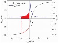
It has been proved theoretically and experimentally that Barkhausen noise reach its maximum at zero crossing, if you use a differential coil simply you just cannot see the maximums, ABBM model (Alessandro-Beatrice-Bertotti-Montorsi) predicts better than most the phenomenom, it is not a typical uncorrelated noise, so if you repeat a technique of the 50’s with actual amps and computers, results must be poor for sure.No Juan. The barkhausen noise is a consequence of external excitation. If no exicitation there is no noise. It has nothing - or at best remotely little - to do with hystereys curve derivative. It is rather related to local "details" of what appears to be a simple curved line (the hysteresys curve itself).
Pierpaolo, this means that when domains flip out, Barkhausen noise reaches a maximum, which is that I have been saying from the beginning.Ok Jaun I found the source of your picture and I am glad to read that it says exactly the same thing I meant above (i.e. it has to do with a minority of motions that are not reversible).
It says: "So far, these two very distinguishable micromagnetic processes have not been separated experimentally in the BHN signal, which
is strongest around the coercivity of the material. At this
point of the hysteresis loop, the dominant process is the
irreversible DW (domain wall) motion, which is associated with those events
of the BHN signal occurring around the main peak. "
This also means that Barkhausen noise also depends on hysteresis.
It may even be a can of sardines, the phenomenon is the same, I did say that do not see the numbers, just the shape of the distribution around zero crossing.The BHN envelope on the picture you uploaded is from out-of-service steel pipelines! It's not GO laminations or any other magnetic core used in audio.
Maybe, maybe not, but with two 80 turns coils connected to avoid the fundamental signal sure it will be a very small signal, sadly, to know how many Barkhausen noise you have in an audio transformer, your set-up must include…an audio transformer, and you must do a lot of measurements and then integrate over the audio frequency range.If you look at the envelope measured on magnetic materials used in transformers the peak of the envelope goes from micro-volts to fraction of millivolts. It is a very small signal (and its byproducts as well), well below the noise floor of the best home audio amplifier you can build.
Anyway, Barkhausen noise is a side effect, and I have not a clue if it is relevant or not for audio transformers.
Remind you that zero crossing problems do not finish with Barkhausen noise, what about losses and linearity?
Did anybody measure how much crossover distortion is due to transformers?
Whoa, domain flipping has been passed from mass flipping of domains to misuse of language and now to an accepted expression. That is good; it means that you are learning, sadly, is you who create confusion.I repeat: moving a domain wall (so that domains grow or shrink) is not the same as flipping a domain. Flipping a domain is, as you say, flipping a domain. Growing a domain by moving a domain wall by flipping some spins, which is what can happen when the external field changes, is not flipping a domain. You fail to distinguish between these two quite different situations, and so create confusion.
To move a domain wall, it must flip the neighbor domain, or part of it if its intrinsic magnetic moments are strong enough.
Is this so difficult to understand?
This is much better, using a single coil, the peaks appeared, as was predicted.Here is one example of BN noise resulting from zero-crossing in two types of magnetic steel...
For each of the two alloys there are three variants. From fig. 3 it can be seen that the one with higher Hc and lower permeability has the lowest noise. The one with lowest Hc and highest permeability has less noise than the third one. So no noise can be derived by looking at the B-H curve.
http://ac.els-cdn.com/S030488531400...t=1486052585_2d0df69aa4616075cd7af0b99f1c587f
In the worst case the peak noise is in the mV range.
As for the numbers, show me the same research with an audio transformer, only so we will know if Barkhausen noise is relevant or not.
By the way, for only three laminations it needs a lot of turns! 😀
Last edited:
Sorry Juan, I have just shown you that even if you cross the zero the intensity of the signal is not boosted! The order of magnitude is the same. Yes, it depends on hysteresis because the coercive field is the first indicator of irreversible processes but you can't figure it out from the B-H curve. It depends on the material and the way it is used. As I have a PP amp and a SE amp in front of me I cannot detect any random noise like that from my PP amp by direct comparison. Zero. Actually at low output level the PP amp is superior probably because has less distortion of any kind and is quiter. I don't need examples that have nothing to do with audio amplifiers.
And even in presence of some occasional random noise, never forget that it NEVER affects the audio performance because it is immediately bypassed by our brain as it brings no information about the musical signal.
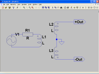
The very simple experimental setup given in post #6 gives away the whole deal.
We used to do this same demo in high school class with a telephone coil and tube amplifier. There is continuous BH noise as the magnet approaches the core, and again as it recedes. This shows right away that the noise persists with a DC field applied. Any change in H flux through the core must change domain orientations. The peak in BH noise occurs where the permeability is maximum because domain avalanching occurs. It is where the B-H curve has the maximum slope.
A gapped SE like xfmr still has B-H loops around the DC operating points, they are just smaller since the permeability is much smaller. More magnetizing current must be applied to get the flux to change. And for the same output AC voltage, the same amount of flux must change. So you are stuck with high magnetizing current. Not good. Keep in mind that AC voltage out has to do with flux change only (which is controlled by input voltage only). There is no noise or even distortion mechanism interceding in series, as so often seems to be assumed. The noise and "distortion" (just magnetizing current) shows up in the magnetizing current imposed on the driving tube. If the tube cannot handle the magnetizing current ( high Rp), then voltage distortion will occur in the driving source.
What has been left out so far, and is most important, is the output impedance of the driving source (tube). If the tube is low Z output, the core is strictly controlled. Domains only "flip" when NO voltage constraint is imposed. Low Z output forces the domain walls to slowly rotate (or propagate) into the forced directions. Flux is strictly controlled. No B-H noise occurs under these conditions (zero Ohm driving). And even if it did, it would have no effect on the voltage of the driving source anyway. The drive voltage is directly transferred to output V except for leakage L losses (and leakage L flux does not even go through the core material).
So the solution to eliminating xfmr distortion and noise is low drive impedance.
Unfortunately, this is the most common failing of SE designs with excessive triode output Rp. Some local N Fdbk can fix this of course.
So tube output Z is the real issue for either SE or P-P. High permeability makes it easier for the tube due to lower magnetizing current to deal with.
Last edited:
Curiously, in the paper you posted, figure 3 shows clearly the BN peaks at zero crossing as theory predicts.Sorry Juan, I have just shown you that even if you cross the zero the intensity of the signal is not boosted!
Anyway I do not favor PP or SE either, even worse, I hate transformers, long ago I promised myself to not wind output transformers anymore, just power transformers and hybrid amps.
Totally agree, stupid me, I posted a link to the same video on post #17.The very simple experimental setup given in post #6 gives away the whole deal.
Sometimes simple experiments are the best, but you know, it is easier to split an atom than a prejudice.
Domain avalanching occurs almost on the whole hysteresis loop, it is minimum at both saturation extremes and maximum at zero crossing due to maximum movability of magnetic domains.The peak in BH noise occurs where the permeability is maximum because domain avalanching occurs. It is where the B-H curve has the maximum slope.
Magnetizing current is not an evil per se, waveform is that matters.So you are stuck with high magnetizing current. Not good.
I can wind a transformer with low magnetizing current but even non-sinusoidal, on the other hand, an air gap can slow down magnetic permeability about two orders of magnitude, greatly increasing linearity, and magnetizing current is greatly increased too.
Domains only "flip" when NO voltage constraint is imposed. Low Z output forces the domain walls to slowly rotate (or propagate) into the forced directions. Flux is strictly controlled. No B-H noise occurs under these conditions (zero Ohm driving).
No, as I said before, domains flip almost all over the hysteresis loop, you can think that the magnetic field B “sees” the primary voltage and the magnetic field H “sees” the magnetizing current.
Yes, but the order of magnitude doesn't change.
Curiously, in the paper you posted, figure 3 shows clearly the BN peaks at zero crossing as theory predicts.
Solid state amplifiers have other issues. Some even worse than valve amps!
"No, as I said before, domains flip almost all over the hysteresis loop"
Poor choice of words on my part there. Domains do not generally "avalanche" when the voltage is constrained. What I was getting at is that domains must gradually rotate or push their boundaries under voltage constraint (Zimp = 0). If the voltage changes very slowly, then the domain boundary spins must gradually angularly rotate into flipped position to satisfy Faraday's law. A high impedance is required for spins and domains to spontaneously do their own thing.
On a more microscopic level, even under voltage constraint, spins or domains may indeed flip spontaneously, but the other domains being held in angular positions will "back react" by some small angle to preserve the net core flux per Faraday's law (some small additional compensation in the vacuum field too). So the "net observable" effect is to disallow spontaneous flips, etc, as far as the external world (the winding V) sees (under strict voltage constraint).
----
Magnetizing (sine wave portion) current is generally 90 degrees out of phase with resistive load current. So it should be considered "distortion" in that sense. Or at least considered as reactively modifying the load impedance.
-----
The interesting challenge is how to make a better xfmr. There are schemes that use N bifilar 1 to 1 xfmrs, with common mode chokes used to series connect primaries while parallel connecting the secondaries.
Then there is the switch-mode (HF carrier) technique, like the Berning impedance converter. (high leakage L however). And even most any voltage multiplier technique can be used with a HF carrier. (Cockroft-Walton V multiplier ladder for example, or resonant structures)
Even a tapered transmission line impedance conversion is possible in theory. Ridiculously long at 20 Hz however. In practice, loading it with magnetic cores along the entire length could could shorten it by a factor of several hundred. (Sqrt of L in the wave velocity factor I think)
..
Last edited:
Yes, but the order of magnitude doesn't change.
The blue peak goes from about <0.1mV to about <2.5mV and the red peak goes from about <0.1mV to about >1.5mV
Here in town we call this a change on one order of magnitude… 😀
I do not understand your point, but if you want that voltage changes very slowly then you have two possibilitiesIf the voltage changes very slowly, then the domain boundary spins must gradually angularly rotate into flipped position to satisfy Faraday's law.
i) Use ultra low frequency
ii) Use time dilation
Last edited:
The blue peak goes from about <0.1mV to about <2.5mV and the red peak goes from about <0.1mV to about >1.5mV
Here in town we call this a change on one order of magnitude… 😀
You lost the original sense of that. The order of magnidute is not referred to the peak itself but is a comparison with the other method relying on minor loop with no zero-crossing instead of B-H loop that you didn't like. You can see both in the article I posted! Here in town a 2 mV RMS of the peak is of the same order of 0.5mV RMS of the minor loop. An order of magnitude is a factor of 10. There is only 1 case out of 6 where it is almost there but there are 4 where it is not even a factor of 2! And this is not transformer core material, yet...
You put a picture of un-specified material where the peak value is in the volt range to compare with the real thing (GO laminations) that displays a signal 3 order of magnitudes lower! Unfortunately your picture refers to out-of-service steel pipelines (possibly also with poor magnetic properties) that very likely had a lot of stress and all sorts of defects or even damage. Of course BN signal was so big.
Last edited:
- Status
- Not open for further replies.
- Home
- Amplifiers
- Tubes / Valves
- SE OPT Arcana