> If a high enough signal drives the output tube close to Vgk=0, then the cathode will get lower in voltage, so changing the bias.
Is this a Hi-Fi amp? Or a guitar amp?
In hi-fi, clipped peaks will normally be rare and quick; else it sounds nasty and we turn it down.
Yes, guitarists do slam their amps into prolonged overdrive. But they want the tonal shift.
I think the cathode should always have a low AC impedance.
And BTW: typically the cathode voltage (bias) does not rise, the grid voltage is clamped on the positive peaks and the average grid voltage (bias) goes negative. "Grid Blocking". It is a signature sound for some guitarists.
If you must fret about frequent positive-grid events taking the cathode positive, use an R with a C, measure the happy cathode voltage, and then add a Zener a few volts higher so the cathode can not rise much. Grid-blocking can be greatly reduced with a series grid resistor roughly half the size of the grid leak resistor (semi-equalizes time constants up and down).
It is a hi-fi amp.
Using cathode bias, the mean cathode voltage does fall, either if using a bypass capacitor or not. You can simulate it in LTSpice easily. Once the grid is positive enough, it shifts bias. Keep reading, I'll get back to this one paragraph later.
I added a bypass capacitor in the cathode and repeated all measurements. Obviously, this didn't change the primary inductance measurement, but it made core saturation happend a little bit before (at a higher frequency), and I got a little bit more power output. No surprises. On the other hand, the OPT performance is very similar, and the "cutoff" I mentioned in post #12, still happends.
I think this could be problem to the cutoff behaviour:
The signal level I choose as "max output level just before clipping at 1 kHz" was not really that. Saturation was already happening, but was not obvious, as only cutoff showed a hard clipping.
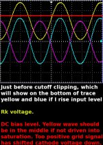
Attached, you can hopefully see what I mean. The top of the yellow trace is rounded, but had clipped long before reaching that level. Saturation is just soft, not hard, and it hides the clipping. If I take the "max signal before clipping at 1 kHz", as the level prior saturation (much positive grid level), then I can get a great performance down to 18 Hz. Of course, less power. No miracles.
>
And BTW: typically the cathode voltage (bias) does not rise, the grid voltage is clamped on the positive peaks and the average grid voltage (bias) goes negative. "Grid Blocking". It is a signature sound for some guitarists.
Using cathode bias, the mean cathode voltage does fall, either if using a bypass capacitor or not. You can simulate it in LTSpice easily. Once the grid is positive enough, it shifts bias. Keep reading, I'll get back to this one paragraph later.
I added a bypass capacitor in the cathode and repeated all measurements. Obviously, this didn't change the primary inductance measurement, but it made core saturation happend a little bit before (at a higher frequency), and I got a little bit more power output. No surprises. On the other hand, the OPT performance is very similar, and the "cutoff" I mentioned in post #12, still happends.
I think this could be problem to the cutoff behaviour:
The signal level I choose as "max output level just before clipping at 1 kHz" was not really that. Saturation was already happening, but was not obvious, as only cutoff showed a hard clipping.
Attached, you can hopefully see what I mean. The top of the yellow trace is rounded, but had clipped long before reaching that level. Saturation is just soft, not hard, and it hides the clipping. If I take the "max signal before clipping at 1 kHz", as the level prior saturation (much positive grid level), then I can get a great performance down to 18 Hz. Of course, less power. No miracles.
Attachments
It is a hi-fi amp...., the mean cathode voltage does fall, .... You can simulate it in LTSpice...
With speech/music signal? Or with a steady Sine?
"Hi-Fi" output will not be MAX long enough to de-bias.
I was talking about pure sine wave, of course.
If someone is curious, I finished a whole lot of tests: triode and pentode, several output levels, several bias points, several gaps and loads,... Using no air gap material at all is good enough for up to 50 mA Idc. The core does not saturate at frequencies above 20 Hz. The problem was, indeed, the small Lp. This sets a limit on how much power I can take out of it with the best THD possible, but it handles the low power of the amplifier well enough. Some GNFB helps, without compromising stability.
If someone is curious, I finished a whole lot of tests: triode and pentode, several output levels, several bias points, several gaps and loads,... Using no air gap material at all is good enough for up to 50 mA Idc. The core does not saturate at frequencies above 20 Hz. The problem was, indeed, the small Lp. This sets a limit on how much power I can take out of it with the best THD possible, but it handles the low power of the amplifier well enough. Some GNFB helps, without compromising stability.
- Status
- This old topic is closed. If you want to reopen this topic, contact a moderator using the "Report Post" button.