SET12 said:
When the supply gets up to about 6-700uf any noise is gone in my experiance a great sounding tube I'll try and post a pic of mine! I think you'll love it's looks, you can then connect the output transformer center taps direct to the rectifiers cap the 6-700uf you can use 5-10 K to feed another 50-100uf and be set! I use only about 5 to 6db feedback in mine! A slow turn on rectifier like a 5AR4 works good or GZ37 that I use with the 1800 UF in my SET
I will be limited the next couple of weeks for posting due to my daughter being with me for a couple of weeks.
I have an idea to pursue that would allow any tube rectifier to be used without arcing it over but I just haven't given it a shot yet!
Erik, and anyone else!
Another methode that I use for speed and isolation of supplies I found in an old early sixties solid state manual was the use of Diode Isolation use a 3 section pie filter Rectifier feeding the fist cap, A diode with anode connected to it along with another diodes anode connected to it feed the cathodes to your favorite high quality cap such as a Solen or one of you choice! Those two high quality caps will have some 80 db isolation from one another! you can use other pie configurations as well including one to isolate the left and right channel supplies as well!
On another note I don't use resistor self bias with bypass caps I got turned on after reverse engineering a phono stage that used LED biasing after comparing it was a no brainer for me and I have never looked back Very Dynamic!
An externally hosted image should be here but it was not working when we last tested it.
The Hammond 1628's have an excellent bass-region response, dynamics and "body". I wonder if you have tried to put some negative feedback on your amp.
The bass with these transformers is not the issue, it is the best bass that I have heard through my small speakers. I tried them for a few minutes through my 15 inch open baffle spaekers and it shook the walls good with only 8 watts. I have tried cathode feedback with each of the secondary (speaker) taps and found that there is some improvement, but it is not as obvious as with a smaller transformer (which has more room for improvement).
I recently ordered the pair of 1628's from a well known distributor and received a pair that are two years old. I discovered severe ripple (6 db) in the 10 to 20KHz region. This appears to be a phase problem with the two windings that you connect in parallel for 4 or 8 ohm output. I have since found that this was a known issue with transformers of this vintage, and was the reason that Hammond changed their secondary to a single tapped winding. The problem is not as obvious with all of the secondaries in series (16 ohm) and this is how I have them connected currently. This presents the tube with a non - optimum 2500 ohm load. Maybe I will just add two more tubes!
I haven't decided what to do with them yet. I could try to return them, but shipping is $25 each way. I am still experimenting with them to find a circuit that will make them happy.
I am looking for a good transformer to use in SE amplifier kits, and it won't be these. I would have liked to try the newer style Hammonds, but that is not what they sent. I have the large Edcor SE transformers on order, I will wait to see what they do. Their little ones are amazing for $18!
I have been using some motor RUN capacitors that I got on Ebay. 100uF at 370 VAC, they are $12 each. Adding one from the OPT B+ terminal to ground makes a big improvement to the sound, a second one makes a small improvement. I notice no benefit to any more caps. This is a 8 watt (triode) to 15 watt (UL) SE amplifier using EL-34's, 6L6GC's or 6550's.
Petralias Nik said:The Hammond 1628's have an excellent bass-region response, dynamics and "body". I wonder if you have tried to put some negative feedback on your amp.
My first implementation was the direct-coupled Mullard 3-3 circuit with global feedback. The high frequency response went from a null to a very sharp peak of a couple decibels at 13 kHz. The 1628 was a seriously defective design.
I have been using some motor RUN capacitors that I got on Ebay. 100uF at 370 VAC, they are $12 each. Adding one from the OPT B+ terminal to ground makes a big improvement to the sound, a second one makes a small improvement. I notice no benefit to any more caps. This is a 8 watt (triode) to 15 watt (UL) SE amplifier using EL-34's, 6L6GC's or 6550's.
Have you ever tried a pie filter useing Diodes to drop the noise over? My amp runs on 500volts, The driver stage does also and is only isolated by diodes as well As mentioned I use LED biasing on my first gain stage, And there there is one heck of a Thread on LED biasing I see in my opinion the DCR of you choke may still be in the way and adding 100uf is not much of a change so I wouldn't expect it to be real audiable I think its got to be alot more and looser I also suspect that the ACR of the choke may get in the way as well! I have seen once of some guys designing what they called loose regulators meaning the ACR was low
I have some polyprop and oil ASC motor run caps as well that I auditioned once I found that they just weren't as transperant as a solen.
Another thing that I did was to use diodes to connect the DC filament supply to my 572 instead of resistors ( the thought of doing it was that I didn't want to use anymore current and I wasn't to keen on any bias fluctuation) as it runs at 0 volts bias formerly it had the negative leg of the DC grounded which I'm told reduces the life of the tube when I did this the dynamics went thru the roof so much so that my neighbor called to say that her pictures were vibrating on her wall the amps had been running already for a year! And our living rooms were seperated by garges from one another!
Dan
An externally hosted image should be here but it was not working when we last tested it.
SET12 said:
Have you ever tried a pie filter useing Diodes to drop the noise over? .....
YYYYEEEEEEEAASSSSS !!
Diode rules!
Thanks a lot for sharing this method.
These days I've been experimenting this. At first I modified the pre amp, which is a 5842 with OPT. The power supply is originally many stages of LC & RC. I kept the chokes at the front, & replaced all RC with DC (diode-capacitor). And for keeping the original operation voltage, I skipped the first little C after rectifier to make it a pure choke input filter. The voltage drop here compensates the lost of series R's quite well.
The result is: LCDCLCDC<DC<DC
( "<" above means split, so it's 1 to 2 to 4 )
TBH, at this mod I didn't hear very much difference. And the improvements are mainly in mid-high range. The sound seems crisper & clearer. As mentioned, the difference is subtle.
I guess, maybe, in the original circuit, the last big C's (1000uF) dominate the overall supply behavior. They are one for each tube, so the energy storage has been already far more than needed. The clearer mid-high might be brought by the improved channel isolation & lower supply impedance.
Then I modded the 6C45 single stage amp. It's oringally CL<CRC. I modded it into CLC<DCDC. This amp is only serving from 160Hz & up, so I can not evaluate its bass. Again, like the pre, sound seems slightly crisper & clearer.
It's not that I purposefully delay the mods on the bass amp, I was waiting for the caps, which was going to be added into the last stage of "DC".
The original power supply is separated CLCLCLC for ouput stage & LCLC for driver. It's a stereo & both channel share the same supply.
With additional caps & diodes, I made the one for output stage into CLCLCLC<DC, and driver LCLC<DC. The last C for output stage is 330uF, and the one for driver is 220uF.
I know the C's are not very big, however, at least it's now one for each tube with a diode in front of them for good isolation. And, with all these additional capcitors, the limited chassis space is full. I can not squeeze in more, even if I want.
The sound, the sound!
YES! Very good bass!
I use this 300BSE, configured to about 4~5W only, to drive 2* 18incher per side and play a DVD with many explosion & crashing sound effects

It's awesome! It's shaking the door/ window & furniture. It's not that I haven't expericed the shakings, they just didn't come from this amp. Now it's not only loud, it's solid & punchy, it's controlled & no boomy.
Switch to some other "normal" materials, the improvements on bass is obvious. The deeper it goes, the more obvious the improvements are.
For example, the album "Are We There Yet" (by Steve Swallow & Carla Bley), a very simple piano & bass combination, the bass extension is phenomenon. http://www.amazon.com/gp/product/B0000258KY/ref=sr_11_1/102-4718600-5336909?ie=UTF8
Supposedly deep bass is not from the instruments themselves, it might come from the reverberation of the recording space or vibrations of stage, commonly appeared on many live recordings.
On the RTA screen of DEQ2496, there are bursts in 20~40Hz range following each attack of bass note. And there are also some paddle "noise" from piano at about the same range.
With the mods on power supply, now this 300BSE can make a very good & complete presentation for such live recording material, all the way down. I'm very happy with the results.
And, how amazing these dirtcheap diodes can do! My system got an overall upgrade, with so less cost.
Thanks again SET12😉
Now I'm thinking how to mod the cathode bias to fix bias on this direct-couple circuit.....
Glad to hear you like the results!
I usually dial the noise floor in by ear tolerance we all have our limits but as you can see excess noise free has its trade offs.
yes fixed bias well yield more dynamics but have you tried Zener biasing with a bypass cap in the same range that you would for a cathode bias resistor?
Thanks for the Bass CD recomendation I will certainly pick it up!
SET12
For 300B's cathode, I'll need 65V zener, with 5w dissipation.
Wow, that's a big one!
And how do they compare? I mean zener vs resistor.
Wow, that's a big one!
And how do they compare? I mean zener vs resistor.
I would use a pair of diodes with their Anodes connected to the filament leads like resistors that are commonly used and the diode cathodes connected together at the top of the zener and bypass cap.
This should lower the DC voltage bias fluctuation greatly for self biasing.
I would think it should have the same effect as the two diodes connected to my own 811 filament did as it is running in Class A2 with zero bias actually it is maybe -1 volt or so formerly it had a DC supply with the negative leg grounded which reduces tube life.
When I used the diodes with the cathodes grounded the dynamics of my amps went thru the roof! So much so that I got a call from my nieghbor that her pictures were moving on her walls our living rooms were seperated double garges between us needless to say it was a jaw dropping experiance!
SET12
Thanks for the tips on filament🙂
I'm thinking, if the cathode resistor is replaced by a zener, then we should call it fixed bias. In this case, it makes a fix positive cathode potential, instead of the common negative grid. Am I right?
Here I came out a simplified circuit diagram of my amp.
(Sorry I can not give a detail one because I bought this amp instead of built it from scratch, even I modified it a lot. Without the permission of the seller/designer, I'd better not publish the detail circuit, even though it's quite simple.)

Thoughts on DC bias fluctuation: yes, it would flucturate by the current change, but a current "change" is AC. Then AC should be shorted to ground by the bypass cap. And if that cap is large enough, its effective range should approaching DC.
In my case, I use 150uF to bypass 900R. That give me a -3dB point of 1.18Hz. Is that still not big/low enough?
OK, change the cathode resistor to zener could bring it all the way down to DC. But there's still another bottle neck- OPT. So in the real world, how big is the effect?
Then, I'm thinking, if zener is used, I got a fixed cathode bias. So, why not a "real" fix bias?
pro:
1. The original supply for output stage is fully utilized. No more "waste" on the cathode. I will get some more power from it.
2. No more bypass cap in the way.
3. Probably superior clarity, dynamics & controlled bass.
con:
1. No free lunch, an additional bias supply is needed. (no big deal if SS rectifier & regulator are used)
2. This amp is a stereo one, the "ground of output stage" can not be splitted. So both channels can not be set up individually. Matched pair of tube is needed.
3. No more auto adjustment by cathode current. Additional bias current monitoring & saftey circuit are needed.
Any thoughts?
Thanks for all opinions.
🙂
I'm thinking, if the cathode resistor is replaced by a zener, then we should call it fixed bias. In this case, it makes a fix positive cathode potential, instead of the common negative grid. Am I right?
Here I came out a simplified circuit diagram of my amp.
(Sorry I can not give a detail one because I bought this amp instead of built it from scratch, even I modified it a lot. Without the permission of the seller/designer, I'd better not publish the detail circuit, even though it's quite simple.)
Thoughts on DC bias fluctuation: yes, it would flucturate by the current change, but a current "change" is AC. Then AC should be shorted to ground by the bypass cap. And if that cap is large enough, its effective range should approaching DC.
In my case, I use 150uF to bypass 900R. That give me a -3dB point of 1.18Hz. Is that still not big/low enough?
OK, change the cathode resistor to zener could bring it all the way down to DC. But there's still another bottle neck- OPT. So in the real world, how big is the effect?
Then, I'm thinking, if zener is used, I got a fixed cathode bias. So, why not a "real" fix bias?
pro:
1. The original supply for output stage is fully utilized. No more "waste" on the cathode. I will get some more power from it.
2. No more bypass cap in the way.
3. Probably superior clarity, dynamics & controlled bass.
con:
1. No free lunch, an additional bias supply is needed. (no big deal if SS rectifier & regulator are used)
2. This amp is a stereo one, the "ground of output stage" can not be splitted. So both channels can not be set up individually. Matched pair of tube is needed.
3. No more auto adjustment by cathode current. Additional bias current monitoring & saftey circuit are needed.
Any thoughts?
Thanks for all opinions.
🙂
I have seen your present status in a design here in the U.S. and there is no question its pretty nice! I find Mods 1 and 2 of no real enhancement and Mod 2 would cut off the 300B!
Its the DCR of the choke that makes the Present Status work!
I work nights and it is morning, so it took me a bit before I reconized it when I first ran across this I studied it for several hrs with a lot of thought as to how I could accomplish it using resistors instead of the anode choke loads and use just about any values I wanted to, Which I did! But unforunately I can not discuss it, I also can use current source loads as well with my solution.
Glad to see the LED biasing of your driver Definitely superior to resistor biasing.
I have read of people using up to 1000uf to bypass on driver tubes and I think they like it because of the longer time constant to charge which keeps the bias more stable like the LED but still not as effective as an LED you might try a bypass across the LED as well and be carefull as to which LED you use you want to use one near the top of its current range check out the LED thread under Tubes as it has some valueable imfo!
What size are the anode chokes and BTW the 6C45 is one heck of a tube! I never really looked at it before wow what a monster!
More later I got get some sleep!
SET12
I don't understand why mod 2 will cut it off. 😕
Here is the inside of the amp:
As can be seen, the anode choke of driver is rather small, about 5~6cm per side. 17~18mA DC through it cause about 3V drop, so the DCR is about 180R range. I'm not sure about the inductance.
Here is the inside of the amp:
An externally hosted image should be here but it was not working when we last tested it.
As can be seen, the anode choke of driver is rather small, about 5~6cm per side. 17~18mA DC through it cause about 3V drop, so the DCR is about 180R range. I'm not sure about the inductance.
CLS,
I'm at work on lunch with plenty of coffee in me now!
Anyway after looking at things this what I see!
With # 2 mod my intial reaction was you were going to add a bias of -70 volts which would cut it off! but I see you mean the -5 volts so it will work!
The drop across the Anode choke must be around 66-67 volts or so with a DCR of some 850 ohms or so.
After rethinking about this yes I think either a string of LEDs or zener would be worth a try as the choke will resist any current change which is better than a resistor and because of this the voltage should be more constant!
Got to go!
SET12
SET12 said:CLS,
I'm at work on lunch with plenty of coffee in me now!
Anyway after looking at things this what I see!
With # 2 mod my intial reaction was you were going to add a bias of -70 volts which would cut it off! but I see you mean the -5 volts so it will work!
The drop across the Anode choke must be at 18 ma. around 66-67 volts or so with a DCR of some 3750 ohms or so. Add the 5 volts of self bias and that will put you at your -71 volts of bias for your 300B
After rethinking about this yes I think either a string of LEDs or zener would be worth a try as the choke will resist any current change which is better than a resistor and because of this the voltage should be more constant!
Got to go!
SET12
Don't know the editing system here! I made an error in my math on the DCR of the Anode Choke and saw this later! so the only thing I could do is make the change in a Quote of myself! after wards I saw an edit tab here I take it you must edit immediately or you lose that option!
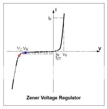
For zener under cathode for bias voltage, I have some concerns.
I got several 5W 12V zener diodes on hand (1N5349B). I intend to stack 5 of them in series for 60V.
What I'm concerning is at the the rating reverse voltage (Vz=12V), the current is 100mA (Izt). On the diagram, it's right above the red dot.
But, in my amp, there won't be 100mA DC flowing through, it'll be likely in 60~70mA range. Then what will happen? Around the blue dot?
What we want is constant voltage in various current, that'd be on the left side of the curve, left-under the red dot.
If I fail to get there, I got an opposite situation! Around blue dot, current change little in a wide range of voltage.
Or maybe, chances are it will go around the shoulder & no, oscillation?😱
I'm no expert on this, can anyone explain it for me?
Thanks a lot 🙂
An externally hosted image should be here but it was not working when we last tested it.
I got several 5W 12V zener diodes on hand (1N5349B). I intend to stack 5 of them in series for 60V.
What I'm concerning is at the the rating reverse voltage (Vz=12V), the current is 100mA (Izt). On the diagram, it's right above the red dot.
But, in my amp, there won't be 100mA DC flowing through, it'll be likely in 60~70mA range. Then what will happen? Around the blue dot?
What we want is constant voltage in various current, that'd be on the left side of the curve, left-under the red dot.
If I fail to get there, I got an opposite situation! Around blue dot, current change little in a wide range of voltage.
Or maybe, chances are it will go around the shoulder & no, oscillation?😱
I'm no expert on this, can anyone explain it for me?
Thanks a lot 🙂
Hi CLS,
The 5 Watt 12 volters are likely to drop out leaving the tube unbiased and an open circuit.
I like to use a zener near the top of its current range yet within its wattage range as well
Looking at NTE Data Sheets you will see a test current and max current you always want to be above the test current spec and yet within the max spec.
I found the NTE 142A 1 watt to meet your requirements its 12 volts test current was 20 ma and max forward voltage IF of 200 ma
So its a matter of picking the right one for the job I am no expert either here but I understand their needs to operate properly
I often have seen zeners stacked in voltage regulator circuits and have wondered why it must of been related to the zeners internal impedance better yet that I think of it! The available current may have been an issue as well! perhaps someone could answer our thoughts here?
here is NTE's site
http://www.nteinc.com/Web_pgs/device_list.html
I found a 5 watt 60 volt NTE 5149A that would work tested at 20 ma and an IFV of 79 ma which I don't like and it has an impedance of 40 ohms at test current
Looking at their 5 watt 30 volter NTE 5141A is much better tested at 40 ma with IFV of 158 ma its internal impedance is 8 ohms at test current
So there are trade offs !
SET12
Thanks a lot. That makes perfect sense to me. After browsing several datasheet, I like the 6.2V the best. It has lowest Z, only 2ohm. Even I have to stack more to get the voltage I need, it's still the lowest.
And, inspired by this circuit:
http://www.jogis-roehrenbude.de/Leserbriefe/TH-Loesch-Amp/Th-Loesch-Amp.htm
( -- which I got from http://www.diyaudio.com/forums/showthread.php?postid=755467#post755467 )
On the above modified Opera M500, I saw 2 different cathode resistors on the heater legs. Assumed perfectly splitted 30mA flow through each leg, which are 22k//2.7k & 47k//2.7k. I calculated the voltage across them should be 76.59V & 72.15V. So their defferenc is 4.45V, well, pretty close to the 5V filament supply.
By this, I have an idea of using individual zener string on each heater leg:
How will it work?
Any thoughts?
And, inspired by this circuit:
http://www.jogis-roehrenbude.de/Leserbriefe/TH-Loesch-Amp/Th-Loesch-Amp.htm
( -- which I got from http://www.diyaudio.com/forums/showthread.php?postid=755467#post755467 )
On the above modified Opera M500, I saw 2 different cathode resistors on the heater legs. Assumed perfectly splitted 30mA flow through each leg, which are 22k//2.7k & 47k//2.7k. I calculated the voltage across them should be 76.59V & 72.15V. So their defferenc is 4.45V, well, pretty close to the 5V filament supply.
By this, I have an idea of using individual zener string on each heater leg:
An externally hosted image should be here but it was not working when we last tested it.
How will it work?
Any thoughts?
I think his design was after hum which is why he used different value resistors for the 300B biasing as I don't think he wanted to use a hum pot to null the hum he might have used one to find the null then substituted the resistor values for sound quality! He has done alot of fine tuning.
I like the zener string idea that you have come up with using 6.2 volt zeners! If one fails in a shorted fault no damage will occur to the tube and if one faults open you'll lose the bias current only! I would ocassionally check the bias to check the condition of the zener string.
I also noticed the choke with a ACR bypass which is a cool trick this lowers the ACR as the frequency climbs after all you only need to go after the ripple frequency! The 56 ohm resistor is still to much for my taste I know how damaging a 100 ohm resistor is in the supply path by experiance and I would dispense with the 56 ohm resistor by adding more capacitance if need be a slow turn on rectifier like a 5AR4 does the trick GZ37 sounds even better though beware that currently only NOS 5AR4's are meeting the delay specs as well as the GZ37 does. Once you have a supply path as fast as the one I use the rectifier tube goes to town even over HexFreds.
SET12
Thinking it over, I decided to give up zeners on cathodes. I want "real" fixed bias.
So it's the 3rd bias method on the diagram above.
I marked some voltages to make it clearer:
As can be seen, grid bias is the sum of [voltage drop across driver's anode choke] & [additional bias supply voltage].
The DCR of anode choke is measured as 200R. The voltage drop across it is about 3~3.5V.
As the cathode resistors are out, so the B+ for 300B will get another 60~70V. For such anode voltage, I need about 75~80V bias to make it work properly.
The additional Vbias, regulated or not? I chose not. Because nothing else is regulated in this amp. So I think it'd be better to let them rise & fall simultaneously.
I made a cheapo simple RC filter, many RC of them! 😀 And put a 24VDC relay coil in series with the last filtering stage:
This relay controls the main AC input. If anything goes wrong about the bias supply, the whole amp will be cut off.
I put the whole thing together last night. Things were working properly.
Well, mostly. From the curves on WE300B datasheet, at Va=376V & -77V bias, Ia should be around 80mA, but I got only about 54mA. That's quite a big difference. The tubes are branded "CR", it's a Japaness brand & made in China. IIRC, EH tubes got higher current at the same situation, but I yet to have chance to try them.
And, without the cathode bypass caps, I also lost the WE connections. I got slightly more noise at the output. On the last version of modification, I got 1.3mV AC on the output, now 1.4~1.5mV 🙁
On the table, at idle, everything was stable throughout the 30min's test. Seemed fine to bias this way.
2:00 am, I was exhauted. So no listening test until tonight after work.
Any thoughts?
How will it work?
Are there any pitfalls in the circuit?
So it's the 3rd bias method on the diagram above.
I marked some voltages to make it clearer:
An externally hosted image should be here but it was not working when we last tested it.
As can be seen, grid bias is the sum of [voltage drop across driver's anode choke] & [additional bias supply voltage].
The DCR of anode choke is measured as 200R. The voltage drop across it is about 3~3.5V.
As the cathode resistors are out, so the B+ for 300B will get another 60~70V. For such anode voltage, I need about 75~80V bias to make it work properly.
The additional Vbias, regulated or not? I chose not. Because nothing else is regulated in this amp. So I think it'd be better to let them rise & fall simultaneously.
I made a cheapo simple RC filter, many RC of them! 😀 And put a 24VDC relay coil in series with the last filtering stage:
An externally hosted image should be here but it was not working when we last tested it.
This relay controls the main AC input. If anything goes wrong about the bias supply, the whole amp will be cut off.
I put the whole thing together last night. Things were working properly.
Well, mostly. From the curves on WE300B datasheet, at Va=376V & -77V bias, Ia should be around 80mA, but I got only about 54mA. That's quite a big difference. The tubes are branded "CR", it's a Japaness brand & made in China. IIRC, EH tubes got higher current at the same situation, but I yet to have chance to try them.
And, without the cathode bypass caps, I also lost the WE connections. I got slightly more noise at the output. On the last version of modification, I got 1.3mV AC on the output, now 1.4~1.5mV 🙁
On the table, at idle, everything was stable throughout the 30min's test. Seemed fine to bias this way.
2:00 am, I was exhauted. So no listening test until tonight after work.
Any thoughts?
How will it work?
Are there any pitfalls in the circuit?
Ok! CLS,
I think I got all this now! But correct me if I'm wrong!
The relay circuit is a separate circuit and not your actual B+!
Yes, I like the higher B+
The DCR of the Anode chokes make sense to me now as the rp of the 6C45 is very low!
In a circuit using this similar design they were using an Anode Choke to nearly completely grid bias a 300B with just a few volts made up in the 300B's B+ circuit as self bias.
In your circuit diagram the 5 volts is filament voltage not just 5 volts of additional bias! your circuit was using self bias to achieve nearly all the bias plus the few volts from your Anode Chokes.
You can see why the diagram was a little miss leading for me I should of thought 5 volts filament voltage.
If your 300B filament is DC operated hopefully you are not operating it with the negative leg grounded althought this would be correct! Emission would be from one side reduceing the tubes life by using the diodes in the filament as I suggested will yield substanially improved dynamics! If your circuit is using resistors I would use diodes or them as well!
Is your B+ from SS rectifiers or tube and can you show me what your doing there exactly as it is a critical area for dynamics even more important than the method of bias IMO you could PM me if you don't want to post it.
So far things look good if I'm interpting them correctly!
SET12
SET12,
Your view on the circuit is correct.
And I use tube rectifier, 5R4GY to be specific. (sometimes CV378/GZ37) After that, the filtering is CLCLCLC<DC. The first C is only 1u, and the "<D" means split by diodes. The DCR of first L is 36ohm, 2nd & 3rd are 60ohm, all are 8H.
I'm curious about the diodes under cathode. 2 diodes on 2 filament legs, facing down to ground, can actually even the current?? I just thought the one with higher potential would still flow more (or, all? ). Hmmm ..... In AC filament supply, it should be OK because 2 sides are taking turns, but DC?
My arrengement to this is setting the filament connection on 2 tube in opposite 'polarity'. Swapping channel to channel ocasionally for even wearing. (Learned this from JC Verdier😀 )
OK, back to the listening session last night.
At first, I have to admit, I was dissapointed. This amp is serving from 160Hz and down, 12dB/oct attenuation up. The bass from it was clean but weak. Everything was there but seemed several steps backward. Warmed for more than one hour, the amp was obvious cooler than ever.
I thought to myself, it must be the bad bias point. Not enough current.
Oh, I was so tired of moving the amp, flipping it over, unscrewing the bottom plate, changing parts.... etc. I was so tired 🙁 Blame all the iorns on it.
Switched it off, I changed the tubes to EH, which I remember flowing more current on the same voltage set.
On again, and, YES!! Full body bass was back. As mentioned, I didn't check the actual current. Just plugged it in & gave it a shot. It worked! It's strong & clean.
I have to say I was very satisfied by the last mods on power supply (add more caps & using diodes). Comparing with that, fixed bias mod this time was not so obvious on the "WOW" factor.
It did improve somewhat here & there, but I had to "find" them. And my memories of the previous sound could be mixed up or distorted.
With fixed bias, it seemed more controlled & tighter tension on bass. There was very much energy in 40~50Hz region, relatively less in 20~40Hz. (OK, the speakers should be blamed, too)
So, in the music, acoustic & electric bass are excellent. Drums are also very good. But extended bottom octave from synthesizer are not as good. However, the sound from pipe organ is awesome! Full blasts from the pedals roar like a huge round rock rolling & crushing along.
Looking at the bright side, I think it got the chances to be better. Playing with the operation point will be my next step. (after the recovery of the sore on my back)
- Status
- Not open for further replies.
- Home
- Live Sound
- Instruments and Amps
- SE for Bass?