Soo, 6A3sUMMER, ejam and multi. Thank you for your input about the circuit, but could there be something you are missing? As the circuit designer has test results that say that the circuit in fact works. Vacuum Tube Amplifier / EL156 SingleEnded
Cheers
Cheers
I question the measurement across the 100 Ohm resistor. If it is 4V, and the cathode voltages and plate voltages are also correct, the screen really is dissipating 16 Watts. It does this before you even start the music.
That is a poor way to use an expensive tube that has a screen maximum dissipation of 8 Watts.
Perhaps the plate and screen voltages were measured at different times, with different power line voltages, etc.
The proper way to make the measurement is to measure Across the 100 Ohm resistor (like a floating DMM); and not from plate to ground and then screen to ground.
It would also be a good idea when the amplifier is cold, and when the capacitors are discharged, to verify the resistor is still 100 Ohms.
The original circuit looks OK, with some change suggestions, some of which have already been noted.
Optimize the resistors in the input tube for the tube that will actually be used.
If you never turned the volume up high enough to draw grid current, then the 2uf capacitor will not charge (except during warm up at power up).
Grid current is drawn when the driver voltage swing makes the output control grid to rise more than the voltage the cathode is at.
I am not concerned that the control grid current will destroy the EL156. That ECC83 is not going to do that.
Grid current is not a function of the capacitance. But the capacitance value does affect how long grid current is drawn before the capacitor is charged. And it does affect how long until that charge goes away (the tube is mis-biased until it does).
The control grid that draws grid current may look like a 1 k Ohm resistor to the coupling capacitor.
The charge time constant is capacitance x 1 K Ohm. The discharge time constant is capacitance x 240k Ohms (much much longer to recover). After the large signal, when the signal goes to a lower volume, we are waiting for the capacitor to come to the same voltage as it was before the grid had grid current.
Music is transient. Try to preserve that, and not have the amp waiting to recover.
Jumping around from one schematic to 2 others does require lots more analysis to find what is good, what is bad, and what is OK but needs changes to improve it.
An amplifier can work OK but not be optimum for that particular circuit topology and those particular tubes.
Yes, it is nice when the voltages are marked on the schematic, that at least provides a guide
as to the care of design, and that someone cared to make the measurements.
But the question of the original schematic voltages still remains.
Last edited:
If the rest of the "measurements" are as good as those in the schematic 🙁
And with the two triodes on top of each other the anode voltages gets to low to have some current unless the negative grid voltage is under 1V with grid current as a result = non linear input.Also the first triode shoud be the one on pin's 6-7-8 for less hum.
Then the supply, not to get happy about
Hole lot of stuff to feed the EL156 heaters with DC, useless.And the ECC83 gets AC 😕 with one side ground referenced where there is a center 😡
The power traffo is for Japanese use, 100V in.You have to find another one and adapt the circuit.The rectifier in the schamatic use 6.3V heater, if the transformer has a 5V winding/tap 5Z3, 5R4 or GZ34 are possible.
Mona

Would this be a better circuit?
The 6550 circuit is much, much more promising.
Thanks ketje. The issues you point out are right and this has made my mind up. The project with that circuit is a no go.
Cheers
Cheers
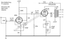
So, what about this circuit? Seems a bit less complicated. Pentode driver is interesting, I have a GM70 amp driven by 6F6. Anyway, please feel free to give me your thoughts about the circuit.
Cheers
Cheers
Attachments
Last edited:
Could function but a bit risky, resistor g1 to ground is 270k where Telefunken says max 100k.You can put the 100k and change the 0.1µ to 0,22µ.Makes the gain EF86 less.Look here, EL156/KT88/6550/KT90 then KT120 Single Ended Amplifier D.I.Y another site from Japan, looks better then the other one.So, what about this circuit? Seems a bit less complicated. Pentode driver is interesting, I have a GM70 amp driven by 6F6. Anyway, please feel free to give me your thoughts about the circuit.
Cheers
Mona
Could function but a bit risky, resistor g1 to ground is 270k where Telefunken says max 100k.You can put the 100k and change the 0.1µ to 0,22µ.Makes the gain EF86 less.Look here, EL156/KT88/6550/KT90 then KT120 Single Ended Amplifier D.I.Y another site from Japan, looks better then the other one.
Mona
Ok, thanks Mona, wonder why he choose a 270K resistor? There are 2 caps without voltage rating, I guess they ar low voltage. Is there a way to calculate the voltage for them 100uf and 4,7uf from EF86.
Cheers
Kanoh-san provided all the relavent data for his design, if you want to critize it, at least, read the article first. Here is the I/O characteristic:And with the two triodes on top of each other the anode voltages gets to low to have some current unless the negative grid voltage is under 1V with grid current as a result = non linear input.
Hole lot of stuff to feed the EL156 heaters with DC, useless.
An externally hosted image should be here but it was not working when we last tested it.
Does it look like "non linear input"? 🙂 The reason for the DC heating is also spelled out in the article here. You can use Google Translate to read the text.
I did, not very interesting.Kanoh-san provided all the relavent data for his design, if you want to critize it, at least, read the article first.
DC heating, he couldn't find the right transfo and hum from finals with the cathode grounded with a big capacitor where he neglect the bigger hum source, from Philips data,
"REMARK
With Vf applied to pins 9 and 4+5 and the centre tap of the heater transformer
connected to earth, the triode section connected to pins 6, 7 and 8 is the more
favourable section of the tube with respect to hum."
That's the transfer function, not the input behavior.With a small -Vg there is some grid current, going up on the positive part of the input signalHere is the I/O characteristic:
An externally hosted image should be here but it was not working when we last tested it.
Does it look like "non linear input"? 🙂 The reason for the DC heating is also spelled out in the article here. You can use Google Translate to read the text.
and down on the negative.That's is an asymetrical load in the input, to be avoided.
Mona
How much grid current could there be for an ECC83? There are literally thousands of input stages just like it, are they all to be avoided? In any case, if you are so fixated on the input behavior, simply change the bias condition. 😉
Grid current starts around -1.2V and goes up to 0.3µA at -0.5V.No big deal for a low impedance source but not nowing what will be used ? I don't jump in the canal just because others do ! If one builds a new amp, better do it right.How much grid current could there be for an ECC83? There are literally thousands of input stages just like it, are they all to be avoided? In any case, if you are so fixated on the input behavior, simply change the bias condition. 😉
Changing the bias ? More -Vg leads to less current and there is allready not much to drive the EL156 (Rg1 max 100k allowed).An SRPP with ECC83 is no good here.
Mona
By a look at the old TELEFUNKEN datasheets I suspect that SE triode mode is a poor choice for this tube. Data only were published for SE pentode mode and push-pull in both triode and pentode mode.
And yes, original TELEFUNKEN's are scarce, rare - and very expensive, unless they are badly worn out (and even in this condition :-(). OTOH, these days' Chinese made "EL156's" don't even deserve this designation, as they don't show the original 10-pin derivative of TELEFUNKEN's German Octal base, but share the EL34's I.O. pinout instead with the immanent threat of arcing between pins 2 and 3 when operated at a plate voltage of 800 Vdc, which is permitted according to the datasheets.
Why don't you use Russian GU-50's instead? Of course, the circuitry needs to be redesigned for this cheap and reliable tube of about the same power.
Best regards!
There are literally thousands of input stages just like it, are they all to be avoided?
Yes!
12AX7 miller capacitance also makes things worse.
Ok, thanks guys for all your inputs, most interesting.
I guess we are seeing several minor challenges in all the circuits I have posted. Anyway, I have made my mind up and going to go forward with a mix. I will use Kanoh´s power supply, tweak it to function with Jenison´s amp stages.
Parts are being ordered and I will be posting as the build starts and will be ongoing.
Cheers!!
Attachments
I see that the amp designer left the V rating out on the caps 4,7uf & 100uf from the EF86 tube. Can anyone help me calculate the voltage, thanks.
Cheers
Cheers
The 4.7uF will see full power supply voltage if the EF86 takes some time to conduct (which they do). I would select a part that's rated for at least 600V.
The 100uF can be very low voltage, but you'll probably find a good selection at 6 or 6.3V.
The 100uF can be very low voltage, but you'll probably find a good selection at 6 or 6.3V.
- Home
- Amplifiers
- Tubes / Valves
- SE EL156 amp