
I will have a look through my calculation spreadsheet. If the both were wrong with a factor of 10 it is probably related.
Adjusted schematic below:

The 7591S simulates well with low distortion for this configuration and drivingpoint as far as I can see, but I use an onlinecalculator:
https://www.vtadiy.com/loadline-calculators/loadline-calculator/
which maybe is somewhat oversimplified.
Adjusted schematic below:
The 7591S simulates well with low distortion for this configuration and drivingpoint as far as I can see, but I use an onlinecalculator:
https://www.vtadiy.com/loadline-calculators/loadline-calculator/
which maybe is somewhat oversimplified.
As i was ordering components I hade to make a few changes to adabt to the suppliers stock of components. The changes were made in the B+ to the 6SN7-tube because it was much cheeper with two 47 uF capacitors than one 100 uF.
I also specified that the 390 ohm resistor to the 7591S should be 5W, which gives plenty of headroom and hopefully no smoke 🙂
I also specified that the 390 ohm resistor to the 7591S should be 5W, which gives plenty of headroom and hopefully no smoke 🙂
Attachments
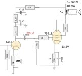
All is hooked up and a few testruns has been made. The B+ is cranked up to 428 V due to less losses than expected in the PSU.
A few other changes has been made as well, as the filtration for the 6SN7 is slightly modified to make the build easier. The cathode resistor is changed to 750 Ohm to get a 28 mA bias to work with the higher anode voltage.
I have tested it with speakers and it works but it has a fair amount of hum which needs to be adressed. Not really sure why it has hum but i will try to sheild the PSU with a box and see if it helps. Otherwise i will look at haveing a rectifier for the heaters.
Measured voltages is in blue down below. The 28 mA is calulated with ohm's law.
Rectifying heaters gives problems of its own, and may not be the solution to the hum anyway. You do have the heater center tap grounded, right? Or at least a pseudo-center-tap. SE amps will conduct power supply ripple directly to the output - since there is no push pull to cancel it. If your supply voltage is high, you can add an RC (or LC) section to the power supply to further reduce ripple. SE-A draws a constant enough current so this is easy.
I think it is most likely a trivial grounding issue. What grounding scheme are you using? Where is the chassis connection?
Some people ground at the RCA plug in, but I think it is better to ground finally at the last PSU filter capacitor as in the Multiple Star ground described here:
Valve Wizard - Grounding
Some people ground at the RCA plug in, but I think it is better to ground finally at the last PSU filter capacitor as in the Multiple Star ground described here:
Valve Wizard - Grounding
Troubleshoot!
Ground the junction of the 1k and 470k grid resistors.
If there is still hum, there are only a few causes:
1. The B+ is not filtered well enough for the 7591 stage (7591 triode wired is Much more sensitive to B+ ripple than 7591 Beam Power mode).
2. The single ended, air gapped output transformer is too close to the power transformer, too close to the B+ choke, and the orientation of the output transformer coils is not at right angles (90 degrees) versus the choke coils and power transformer coils.
3. You used a magnetic steel chassis, and it transmits magnetic hum from power transformer and choke to the output transformer.
4. You have a very bad hum ground loop in the output stage and B+ circuit.
If the hum goes away when you ground the junction of the 1k and 470k, you have:
Either an input stage ground loop.
Or, a B+ ground loop.
Care of ground loops is an art and a science.
A central crows foot ground is actually often a cause of a ground loop.
Example:
Take a full wave B+ supply. Connect the secondary center tap with a short wire Directly to the negative of the first filter cap.
Then, with a second wire, connect from the negative of the first cap to the negative of the second cap.
Then, connect a third wire from the second cap negative to the amplifier's Central ground point.
OK, good!
If instead, you connected the B+ secondary center tap, and the negative of the first cap with wires directly to the Central ground point . . .
You will be introducing the nastiest sounding, highest fast rise transient current, with line frequency, and all the way to frequencies where your ears are most sensitive (kinda sounds like drill motor interference on your AM radio near the old style motor drill.
No DC filaments required for indirectly heated tubes (except some Very bad indirectly heated tubes that are made for the trash bin).
My aluminum chassis amplifiers have less than 100uV hum (< 0.1mV).
Last edited:
In addition to that, some photos of the layout/wiring, could help too.Did you post a schematic of your power supply? I may have missed it.
Big thank you all for your good suggestions 🙂
So, I've had a vacation as it is summer here in Sweden and I have been away from the computer, but I've been reading Valve Wizards grounding guide on the phone as well as some other pieces he has written.
And my coclusions were that the grounding was bad. The chassis is not to be seen as a wire according to Valve Wizard and the biggest groundloop seemed to be from the sheilding of the input cable. But everything was redone with grounding to a single wire attached to the chassis at one point (were the input sheild is grounded).
That solved quite a bit but was far from enought. The amp also had a popping sound when turning it off so extra 47 uF was added to the powersupply. The power supply then consisted of diod rectifier, 5 uF cap, 20 ohm resistor, 50 uF cap, 6,5 H choke, 97 uF cap (50+47). The extra cap seemed to lower the hum as well but I now belive it was just wishfull thinking as we will get to later. The extra cap solved the popping sound so it was still a good modification.
Then I was reading some more on Valve Wizards site and this time about heater and there wiring. There was 3 big problems with the heaters:
All in all, the work with the heaters really paid off and solved the hum! Putting your ear against the speaker it is still there (95 dB sensitivity), but in the room it is not audible. Will try on the main system (101 dB senitivity) when i get some free time
So, I've had a vacation as it is summer here in Sweden and I have been away from the computer, but I've been reading Valve Wizards grounding guide on the phone as well as some other pieces he has written.
And my coclusions were that the grounding was bad. The chassis is not to be seen as a wire according to Valve Wizard and the biggest groundloop seemed to be from the sheilding of the input cable. But everything was redone with grounding to a single wire attached to the chassis at one point (were the input sheild is grounded).
That solved quite a bit but was far from enought. The amp also had a popping sound when turning it off so extra 47 uF was added to the powersupply. The power supply then consisted of diod rectifier, 5 uF cap, 20 ohm resistor, 50 uF cap, 6,5 H choke, 97 uF cap (50+47). The extra cap seemed to lower the hum as well but I now belive it was just wishfull thinking as we will get to later. The extra cap solved the popping sound so it was still a good modification.
Then I was reading some more on Valve Wizards site and this time about heater and there wiring. There was 3 big problems with the heaters:
- wiring
- floating heater
- they were connected in parallell with the input tube in the middle.
All in all, the work with the heaters really paid off and solved the hum! Putting your ear against the speaker it is still there (95 dB sensitivity), but in the room it is not audible. Will try on the main system (101 dB senitivity) when i get some free time
- Home
- Amplifiers
- Tubes / Valves
- SE 6SN7 & 7591S amplifier