Hello,
I'm planning to build this amp:
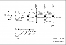
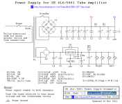
DIY Single-Ended (SE) 6L6 / 5881 Tube Amplifier
I have a 10H choke. So what is better? or what you prefer?
Capacitor based power supply or choke?
Thanks.
I'm planning to build this amp:
DIY Single-Ended (SE) 6L6 / 5881 Tube Amplifier
I have a 10H choke. So what is better? or what you prefer?
Capacitor based power supply or choke?
Thanks.
Attachments

I agree, I think the choke is better provided:
1) It's decent quality, with acceptable DC resistance
2) Your physical chassis design has space for it
3) It can handle the DC current load with an acceptable margin for error
4) You mount it in such a way that it doesn't induce noise in other portions of your system. This can depend significantly on the core geometry.
As far as how you incorporate it, I think it pays to do the calculations here. You want to compute a ripple rejection factor or a transfer function for your filter (I.e. choke and capacitor pair). Also, since you are discussing eliminating a resistor, you need to do the hand calculations to make sure you are getting the correct values for B+ and A+.
Vacuum Tube Power Supply Design
One other thing to add is that you should justify to yourself why the choke is better? Oftentimes the rational is that it gives your power supply a lower output impedance. That's to say that the voltage from your power supply will decrease less per incremental rise in current load with a lower output impedance. Is the improvement rendered by the substitution of the choke for the caps worthwhile? Taking the time to quantify that may prove insightful.
Thank you very much.
The fact is that I'm not an engineer, and this document are very "expert".
So, my think is.
The original designed power supply is for a 250V transformer:
250V*1.41= 352.5V
My transformer is a 260V, so:
260V*1.41 = 366.6V
Voltage drop across de choke is:
0.150*110= 16.5V
My voltage transformer subtract the choke voltage drop is:
366.6V-16.5V= 350,1V
That is very close to the original recommended transformer. This would be correct for my transformer specs?
Attachments

spoontex,
Cap input filter:
If we neglect the voltage drops due to the power transformer primary DCR and secondary DCR (small to medium) and the solid state diode bridge drops (very small), then the voltage output is:
Secondary RMS Volts x 1.414
260Vrms x 1.414 = 368VDC
Choke input filter:
If we neglect the voltage drops due to the power transformer primary DCR and secondary DCR (small to medium) and the solid state diode bridge drops (very small), then the voltage output is:
Secondary RMS Volts x 0.9
260Vrms x 0.9 = 234VDC
You will need more Secondary volts to get the B+ volts you want.
Do not get discouraged.
I very much like Choke input filters, so I use power transformers that have more Secondary volts.
wow...
so, this way I need to use the cap input filter design, because I only have this transformer...
Nevertheless, what voltage would be needs the transformer for this amp? In case that I will buy a new one and I want to use a choke?
Thank you very much!
so, this way I need to use the cap input filter design, because I only have this transformer...
Nevertheless, what voltage would be needs the transformer for this amp? In case that I will buy a new one and I want to use a choke?
Thank you very much!
Can’t the OP just use cap input filter, with a choke arter the cap? He has the transformer?
If you Google for ‘PSUD2’, there is a simulator tool that can be downloaded where you can try out different permutations of filtering.
If you Google for ‘PSUD2’, there is a simulator tool that can be downloaded where you can try out different permutations of filtering.
Last edited:
Sorry for the self promotion, but see post 50 of this thread, that board might be what you are looking for for the power supply. The board in #40 can also be of use for the LM317 supply in your original schematic.
V4lve lover's free gerbers thread.
Anyway to answer your question, your transformer can be around 250-270VAC 150mA per channel, so either two single ones of 150mA or one big one of 300mA.
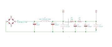
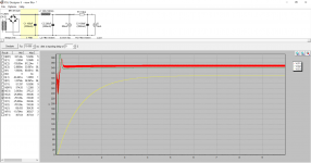
Heres a quick simulation i have done in PSUD2 for the power supply, some more experienced designers will most certainly chime in about the capacitor values.
The program to open .PSU files can be found here:
PSUD2
Cheers!
Edit, i'm currently a little bored, do you want me to design a PCB for the amplifier for free?
V4lve lover's free gerbers thread.
Anyway to answer your question, your transformer can be around 250-270VAC 150mA per channel, so either two single ones of 150mA or one big one of 300mA.
Heres a quick simulation i have done in PSUD2 for the power supply, some more experienced designers will most certainly chime in about the capacitor values.
The program to open .PSU files can be found here:
PSUD2
Cheers!
Edit, i'm currently a little bored, do you want me to design a PCB for the amplifier for free?
Attachments
Last edited:
1. Vacuum Tubes do not drain the B+ caps completely.
Safety First!
Prevent the "Surviving Spouse Syndrome".
Use a bleeder resistor(s) to discharge the capacitors.
2. Use two 25k 10 Watt resistors in series (or one 50k 20 watt resistor), from the B+ to ground (B+ return).
That works for up to 500V B+.
Then re-run the software to see that it did not disturb the results you wanted.
3. Do not stack electrolytic capacitors in series, unless you put resistors across each one to make up for the differences in the capacitor's leakage currents.
Otherwise, if one leaks considerably more current, the other one may be over its voltage rating.
A cap that is near a hot object, such as a hot power transformer, or even worse - an output tube may develop higher leakage current that the one that is in a cooler location. Then the series stacked capacitors becomes an issue.
Last edited:
I'm sorry because English is not my language, and sometime I can explain wrong.
My primary transfomer is:
0 - 260 0.4A
0 - 6.3 2.5 Amp
I assume that I can't use DC voltage for the heater supply, because I haven't enough voltage to use voltage regulator and bridge rectifier. I can only use AC voltage for the heaters. Maybe it down to 5.7V, but it's enough.
My question is: I can use this transformer without modification the circuit? Or I need to do some modification?
Second question is:
I can use a filter choke with this transformer?
Sorry and thanks!!
Sorry for the self promotion, but see post 50 of this thread, that board might be what you are looking for for the power supply. The board in #40 can also be of use for the LM317 supply in your original schematic.
V4lve lover's free gerbers thread.
Anyway to answer your question, your transformer can be around 250-270VAC 150mA per channel, so either two single ones of 150mA or one big one of 300mA.
Heres a quick simulation i have done in PSUD2 for the power supply, some more experienced designers will most certainly chime in about the capacitor values.
The program to open .PSU files can be found here:
PSUD2
Cheers!
Edit, i'm currently a little bored, do you want me to design a PCB for the amplifier for free?
This is wonderful I will try!!
- Home
- Amplifiers
- Tubes / Valves
- SE 6L6 Tube Amp