Hello, I've build this (found somewhere from internet) and it sounds good.
No audio problem, nor THD% change. It seems less booming bass and more available dynamic.
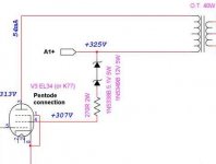
Now screen should work just at little bit lower voltage than the plate. Safe but nearly the max allowed (i.e at plate voltage). But I didn't measure voltages yet.
Any concern about this zener circuitry (instead connecting it, as usual, to the lower voltage power supply of the previous stage via a kohm resistor) ?
Thanks
No audio problem, nor THD% change. It seems less booming bass and more available dynamic.
Now screen should work just at little bit lower voltage than the plate. Safe but nearly the max allowed (i.e at plate voltage). But I didn't measure voltages yet.
Any concern about this zener circuitry (instead connecting it, as usual, to the lower voltage power supply of the previous stage via a kohm resistor) ?
Thanks
Attachments
I have used zeners for screen voltage regulation, but I have not tried in the connection you show.
I would guess that the regulation of the screen voltage in your case, is reliant on enough current flow through the zener diode to ensure regulation.
However, this current must flow through the valve to ground - is this current within the ratings for screen current?
If it is worth anything, I used a zener diode in the conventional way, as the top half of a voltage divider.
The node connecting the zener and current limiting resistor feeds the valve screen, and the other end of the resistor is connected to ground.
Of course, for ex. 200V screen, the zener string needs to be 39 series connected 5v1 zener diodes - or 2 series connected 1N5378.
Using in this way, the screen regulation and THD were greatly improved, in comparison to a simple voltage divider.
Hopefully this is of some help, and if I have lead you astray, then I hope someone more knowledgable will chime in and give better advice.
Last edited:
I have used zeners for screen voltage regulation, but I have not tried in the connection you show.
I would guess that the regulation of the screen voltage in your case, is reliant on enough current flow through the zener diode to ensure regulation.
However, this current must flow through the valve to ground - is this current within the ratings for screen current?
.....
Hopefully this is of some help, and if I have lead you astray, then I hope someone more knowledgable will chime in and give better advice.
Thanks for the kind reply.
Some additional information.
IZK is the knee current of the zener diode. When the current flowing into the zener is larger than the specified knee current, it will permit significant current flow in the reverse direction. For both diodes 1N5338B and 1N5349B IZK is 1mA
IZM is the maximum zener current the diode can handle without breaking. The worst case of IZM is due to the 12V zener 1N5349B which is 395mA (nearly 5W of dissipation)
EL34 Application Data shows a current range of the screen from 8mA at idle to 50mA at full power. A pure pentode with a separate suppressor grid like an EL34 will always exhibit a bit more screen current than a comparable beam power tetrode. KT77 datasheet shows a general 10mA current for tetrode connection.
So everything looks ok to be withing the Zener Breakdown region (zener operating region).
Yesterday I measured voltages.
From power supply 314 Volt, at plate 301 Volt, at screen grid 297 Volt. Practically I reached my goal as the scren grid voltage is now just below the plate voltage.
The source idea for this connection was this:
https://www.diyaudio.com/forums/tubes-valves/116408-ultralinear-zener-screen.html#post1413910
and this:
"A blurb from "The Classic Williamson 1993 Style" by Bill Kleronomos Sound Practices #4:
"An unusual method of applying active screen voltages to the tubes is used. Instead of the usual dropping resistors, I used a set of 5 Watt Zener Diodes for special benefits : screen voltage is always held at or below manufacturer's recommended value regardless of screen current. Distortion products are materially lower because of the stiffer screen supply provided by Zener regulation - this is especially true for the EL-34 pentode with its wider ranging screen current than the usual beam power tubes. And less screen voltage requires less bias voltage and therefore less peak signal voltage from the driver at max. output. Bench tests with EL-34s and 6550s in the output sockets confirmed an approx. 20% reduction in THD when the original dropping resistors were replaced by Zeners."
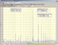
In effect 20% sounds optimistic but I measured 0.11% THD @ 1Watt/8 ohm/1KHz instead of previous 0.14% THD.
LTSpice simulation of my amplifier using KT77 model shows a little more stable voltage at screen grid using zeners to A+, than in the traditional connection using resistor+cap to B+.
I haven't retrieved any additional info to support the correctness of this typology.
Attachments
No concern as such, this is a very benign 'mod'. The screen grid will see a source impedance equal to the raw supply rail (plus the 270R resistor), which may or may not be 'better' than a conventional LC or RC filter.Any concern about this zener circuitry (instead connecting it, as usual, to the lower voltage power supply of the previous stage via a kohm resistor) ?
The Zener does not 'regulate' the screen voltage, it just makes it a bit lower than the raw supply voltage. Since it is only drops about 17V (only 5% less than raw supply voltage) it hardly seems worth it.
Last edited:
I did something like this for a single-ended EL156 amplifier, but had a 75V/5W zener between the screen and the UL tap of the OT.
One zener eventually shorted so put two or three in parallel.
edit: hey you're quoting me!
One zener eventually shorted so put two or three in parallel.
edit: hey you're quoting me!
edit: hey you're quoting me!
Always "render unto Caesar what is Caesar's"

Hmmm… tho' simple, I don't much like it.
For one, it doesn't really deliver regulated sub-B+ to the screen. Indeed, it amplifies whatever ripple-and-noise is on the B+ line by only subtracting a constant voltage. Consider
Of course, this can be 'fixed' quite easily with the Old Bugaboo … a capacitor from screen to ground, to 'hold' the VSCRN, substantially lowering its impedance, siphoning off the VRIP.
Which is what I'd do.
Anyway, probably more fuel than the fire required.
Just Saying,
-= GoatGuy ✓ =-
For one, it doesn't really deliver regulated sub-B+ to the screen. Indeed, it amplifies whatever ripple-and-noise is on the B+ line by only subtracting a constant voltage. Consider
B+ = VRIP + VNOM and then
VSCRN = B+ - VZ … now combine
VSCRN = VRIP + ( VNOM - VZ )
which leaves VRIP unchanged 'on top of' the reduced voltage. If VSCRN = B+ - VZ … now combine
VSCRN = VRIP + ( VNOM - VZ )
% ripple = 100 × VRIP / ( VNOM - Z ) … with real numbers
% ripple = 100 × 0.5 VRIP / ( 325 VNOM - 25 VZ )
% ripple = 0.167% … compare that to B+
% ripple = 100 × 0.5 VRIP / ( 325 VNOM )
% ripple = 0.154%
which is, relatively less on B+ compared to VSCRN. % ripple = 100 × 0.5 VRIP / ( 325 VNOM - 25 VZ )
% ripple = 0.167% … compare that to B+
% ripple = 100 × 0.5 VRIP / ( 325 VNOM )
% ripple = 0.154%
Of course, this can be 'fixed' quite easily with the Old Bugaboo … a capacitor from screen to ground, to 'hold' the VSCRN, substantially lowering its impedance, siphoning off the VRIP.
Which is what I'd do.
Anyway, probably more fuel than the fire required.
Just Saying,
-= GoatGuy ✓ =-
Hmmm… tho' simple, I don't much like it.
-= GoatGuy ✓ =-
Have you considered in your equations that instead of the Zener you should put an extra Kohm resistor in order to equal the drop you have on primary OT and have screen < plate voltage to be safe?
Have to rain on your parade there, but semiconductor devices are made from silicon usually derived from quartzite rock rather than sand. Sand is also silica, often used to make glass, so most electron tubes therefore rely totally on sand for their envelops, and most semiconductor devices aren't made from sand...Tubes don't need any sand to do its job properly. They did it during a century.
Have to rain on your parade there, but semiconductor devices are made from silicon usually derived from quartzite rock rather than sand. Sand is also silica, often used to make glass, so most electron tubes therefore rely totally on sand for their envelops, and most semiconductor devices aren't made from sand…
Well +10 for that, buddy
I am using a similar circuit but enhanced . Make the Zener a power Zener. Used Ron Elliot's an007 circuit. Then from g2 to ground a resistor, value to insure enough current under varying conditions. Bypassed resistor to smooth it all out.
i have tried conventional voltage divider for screen grid supply , zener regulation , VR tubes , Vr tubes +CCS . sometimes i feel it was better but
at the end i always return to basic resistors dividers bypassed with a good film cap .. sonds more natural to me , if you want less distorsion don't use tubes 🙂
at the end i always return to basic resistors dividers bypassed with a good film cap .. sonds more natural to me , if you want less distorsion don't use tubes 🙂
i have tried conventional voltage divider for screen grid supply , zener regulation , VR tubes , Vr tubes +CCS . sometimes i feel it was better but at the end i always return to basic resistors dividers bypassed with a good film cap .. sonds more natural to me , if you want less distorsion don't use tubes 🙂
It is an interesting observation. Since the screen grid on a power output tube may have a screen current of well over 10% of the anode, I do not (generally) advise using 'naked Zeners' … the so-called power Zeners very often have a temperature variance high enough that the power dissipation thru them is enough to vary cold-vs-hot voltage by over 10%.
Instead, I just like using them as a well-regulated fixed voltage reference. With a modest-value resistor and tough but small 'bypass' capacitor to ground, the reference voltage is solid as a rock, and is perfect for applying to the gate of a modestly sized MOSFET series regulator.
The 3 to 8 mA of the regulator, even at a substantially high series-pass voltage (say 100 volts) is still less than 1 W. Air dissipation without a heat-sink is just fine. The Zener, running at maybe ¼ mA, at 300 volts (say), also is not dissipating much power, only 75 mW in this case, barely enough to warm it.
Then again, I also like exactly the same topology for my power supplies. The sweet regulation effect of series MOSFETs with solid gate reference voltages is something remarkable: pretty much hum-free. And that, for less than ¼ the cost of a good quality choke.
⋅-=≡ GoatGuy ✓ ≡=-⋅
decaware use a VR tube in series between the B+ and the grid to lower the voltage on his pentode amp , not really good as regulation but has a nice effect to the sound don't know really why 🙂
For the normal datasheet plate curves with a regulated screen-cathode voltage, then as the plate is pulled down towards the EL34 saturation region, the screen current would increase substantially. In the proposed 'dropper' configuration, the screen voltage may droop somewhat from B+ droop or cathode rise, but the screen would still draw a substantial peak current, especially if the input signal was a large square wave, or the output stage was being overloaded.
A lot of thermal derating needs to be applied to any zener, such that a typical 5W ss zener is often only operated with up to 1-2W max dissipation. Your derating seems fine for that.
If you are making the effort to compare configurations using distortion measurements, then for completeness it would be appropriate to use a common R-Z voltage regulator with Z connecting to the cathode to maintain the screen-to-cathode voltage at circa 300V. You should also try and do comparative IM testing, as the screen is coupled in different ways, and that may show up quite a difference in IM levels.
For the R-Z regulator identified above, a cold-cathode gas tube (eg. 2 x 150V is what was commonly used) is still applicable today.
That has no relevance to the thread unless some comparison is provided as to the noise contributed by the zener and the noise level in the stage under consideration, and if the zener contributes noise above the stage SNR then whether there is a simple means to suppress that noise.Zeners are noisy.
I did something like this for a single-ended EL156 amplifier, but had a 75V/5W zener between the screen and the UL tap of the OT.
One zener eventually shorted so put two or three in parallel.
edit: hey you're quoting me!
Zener diodes in parallel wont do any good, put lower voltage zener diodes in serial instead
Perhaps they may do 'some' good - they may not nicely share current, but they would likely reduce the current (and hence dissipation) of any one zener compared to just using only one zener. Sometimes it comes down to what parts are readily available.
- Home
- Amplifiers
- Tubes / Valves
- Screen grid, zener circuit: any concern?