Hello. Quick question about screen grids current limiters in el34 tube. Have el34 supplied at 430v in pentode connection. For 6k Ra-a found at max power G2 draw 10mA around. G2 Is supplied almost same voltage as the plate , Limiters resistors drop 10v around on 1k stoppers. Still at Ug 420v the grid dissipation is 4.2W. In this conditions I think I can get rid of 1k stoppers and install, say 100ohm just as anti oscillation purpose, because the screens are rated 8W. Should I be concerned from this point to install a certain screen resistor value to be sure the screen dissipation not exceed the max power of the tube please ? As a safe measure I mean.Thanks.
Last edited:

Much depends on the load resistance selection. Some don't seem to realize the optimum load
for pentodes depends as much on the screen voltage as it does on the plate voltage.
As the screen voltage is increased it inflates the entire plate family in a vertical direction.
That means that for any fixed screen voltage the Plate loading needs to increase to a higher Rl
when the plate voltage is increased. That is where one needs to look at the screen current plots,
in particular as the plate current peaks on extreme signals.Throwing darts based on someones
observation that a certain loading 'sounded good' is not good practice.
A further consideration relates as to how the tube will be used. The data sheet values result
as max power into a resistive load. So who listens to that, that kind of loading I don't hear anything.
A real load is reactive & spends much of its time as a high impedance, not an ideal load, say 8R.
Good design partially fixes that by applying a steeper loadline. Some experimenters in the past
have found a steeper loadline results in lower distortion. Something to think about.
Those 5W resistors on the screens could very well be wire wound, so inductive. Not a great choice at all.
One watt is plenty on the screens & should be Carbon Composition (CC). Few people run there amp
at full power for long, that drives the neighbors nutz.
1/2 watt is plenty on any control grid, in fact physically smaller is better. Skin effect gets into the equation,
physically large resisters are no longer resisters at Radio Frequencies. I discovered that as I was working
in a research lab. Making attenuators for 50R transmission line, 2W CC resisters crapped out at 500 MHz.
But 1/2 W CC got me out to 2 GHz. Way beyond audio, but the impedance's were much lower. 👍
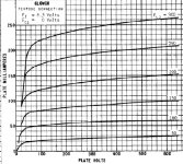
Here are the plate curves of a version of the 6L6 with the voltage on the screen as the variable.
As the voltage is increased at each step, altho the voltage on G1 is fixed at zero, an entire new set of plate curves is formed.
For optimum loading up into the knee of the plate voltage / current curve a different plate loading is required.
This is typical of any common pentode or beam tube. 👍
As the voltage is increased at each step, altho the voltage on G1 is fixed at zero, an entire new set of plate curves is formed.
For optimum loading up into the knee of the plate voltage / current curve a different plate loading is required.
This is typical of any common pentode or beam tube. 👍