Hi,
Inspired by this ( http://www.geocities.com/bobdanielak/technoteNo33.html )
article I decided to give screen grid drive a try a while ago.
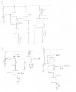
I made a prototype similar to circuit 1 in my drawing:
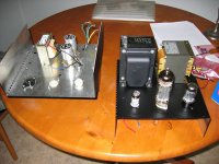
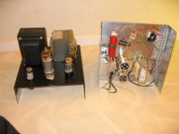
The amp worked quite well (except for some PSU issues that doesn´t belong here), actually good enough to be built properly.
Since the amp is DC-coupled it is sensitive to bias drift, that´s why I used a mu follower input stage.
Long after I made the proto the idea came that perhaps I can get rid of the 12B4 cathode follower if the top half of the input stage already is a cathode follower?
Half a 6SN7 wouldn´t be enough to feed the PL519 (10mA static current and 20mA peaks), but maybe a Mosfet or a high mu, high gm triode would? See drawings 2 and 3.
So, what do you think?
Inspired by this ( http://www.geocities.com/bobdanielak/technoteNo33.html )
article I decided to give screen grid drive a try a while ago.
I made a prototype similar to circuit 1 in my drawing:
The amp worked quite well (except for some PSU issues that doesn´t belong here), actually good enough to be built properly.
Since the amp is DC-coupled it is sensitive to bias drift, that´s why I used a mu follower input stage.
Long after I made the proto the idea came that perhaps I can get rid of the 12B4 cathode follower if the top half of the input stage already is a cathode follower?
Half a 6SN7 wouldn´t be enough to feed the PL519 (10mA static current and 20mA peaks), but maybe a Mosfet or a high mu, high gm triode would? See drawings 2 and 3.
So, what do you think?
Attachments
I use an IRF820 as a source follower to drive the screens in my power amp. It works like a charm.
Thanks for the reple SY.
I´ve pretty much decided to go for the hybrid version with IRF840 (or 820, whatever I find first) and a triode wired E280F.
I´ve pretty much decided to go for the hybrid version with IRF840 (or 820, whatever I find first) and a triode wired E280F.
I'd recommend the IRF820. Acutal in-circuit gm is 100 mA/V which is absolutely nuts compared to valve's.
you could also run a straight triode amplifier, and then CF with a cascoded pair of MOSFET's. The input capacitance of the cascode is quite even and unlike the variable and funky single-gate capacitance. The input gate will be a higher Z load than the DCR of the reference voltage divider you'd use for the bias-ing function.
cheers,
Douglas
- Status
- Not open for further replies.
- Home
- Amplifiers
- Tubes / Valves
- Screen grid driver for PL519?