Say for example you have a two channel amp with PP pentodes in the outputs and a regulated supply for the g2 voltage. What would be the best way to decouple the two channels from each other? Something like the first pic? Also any thoughts on each tube getting its own g2 resistor vs one shared resistor?
Attachments
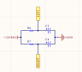
If the source is truly "regulated" there should be little reason to "decouple".
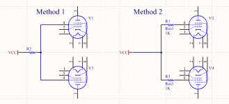
If this is hi-fi, not e-guitar, there is little reason to have a 500-1k resistor in the screen feed. (Over-volted OVER-driven guitar amps do live longer with screen resistors.)
If this is hi-fi, not e-guitar, there is little reason to have a 500-1k resistor in the screen feed. (Over-volted OVER-driven guitar amps do live longer with screen resistors.)
"If this is hi-fi, not e-guitar, there is little reason to have a 500-1k resistor in the screen feed" I can think of two - to stop oscillation and to keep the screen within it's maximum power dissipation limits of individual valves.
Andy.
Andy.
Last edited:
Since a screen resistor will restrict the flow of electrons off the screen and cause a buildup of electrons, a screen resistor will accelerate screen voltage drop and gain shift distortion and so quicken the transition from clean to distortion. Increasing the resistance value of the screen resistor will increase the overdrive screen voltage drop and therefore decrease gain. Lower gain during overdrive causes compression and increases sustain. Adding screen resistance also slows the screen voltage recovery time which tends to have an "averaging" effect on the voltage drop and "soften" the overdrive tone.
As PRR says- "if this is hi-fi,not electric guitar".
Many electric guitar amps are run at their limit to induce distortion and create an impression with their neighbors and in the process burning out the thin screen wiring .
How many genuine audio enthusiasts want to turn up their amps full blast ? that's not listening to music its causing nerve damage to the ears which is unrecoverable.
Good designed amps don't need massive amounts of signal drive to both sound good and clear but a lot of loudspeakers being inefficient need a lot ,its down to -- have a good amp ?--- then buy good speakers .
If the source is truly "regulated" there should be little reason to "decouple".
If this is hi-fi, not e-guitar, there is little reason to have a 500-1k resistor in the screen feed. (Over-volted OVER-driven guitar amps do live longer with screen resistors.)
Oh it’s definitely regulated. A Supertex LR8 regulator driving a pass transistor.
Hmmm… are you expecting more than a few mA to the pair of screens? LR–8 has a 10 mA regulation current capacity. However, having a emitter-follower (BJT/IGBJT) or source-follower (MOSFET) certainly increases the peak current odds.
You might just want to put a medium value (100 µF) capacitor as the “load” to the -follower. Its reactance substantially drops HF screen drive impedance. Indeed … if you were to say that your pair of finals combined nominally use less than 7 or 8 mA, then you could lose the -follower transistor and just have the capacitor there to smooth out the bumps. Has quite a bit of capacity, it does.
PRR's accurate observation notwithstanding, I personally would still include individual screen-feed resistors. Not big values, mind you… maybe only 220 Ω, each.
⋅-⋅-⋅ Just saying, ⋅-⋅-⋅
⋅-=≡ GoatGuy ✓ ≡=-⋅
A while back I made a PCB for power tubes (6L6oids) that included a mosfet follower to drive the screens. I feed the gate of the mosfet from a divider or reference so it acts as a simple regulator. This was for a Unity-Coupled amp that required 4 floating regulators but I use it on other projects as well now since it works and is compact, and I bought like 100 of them. I just feed the boards from B+ and the screens do their thing, all independent from one another.
Screens tied together and run from stable voltage supply (e.g. VR tube) ARE as decoupled as they could possibly be.
Hmmm… are you expecting more than a few mA to the pair of screens? LR–8 has a 10 mA regulation current capacity. However, having a emitter-follower (BJT/IGBJT) or source-follower (MOSFET) certainly increases the peak current odds.
You might just want to put a medium value (100 µF) capacitor as the “load” to the -follower. Its reactance substantially drops HF screen drive impedance. Indeed … if you were to say that your pair of finals combined nominally use less than 7 or 8 mA, then you could lose the -follower transistor and just have the capacitor there to smooth out the bumps. Has quite a bit of capacity, it does.
PRR's accurate observation notwithstanding, I personally would still include individual screen-feed resistors. Not big values, mind you… maybe only 220 Ω, each.
⋅-⋅-⋅ Just saying, ⋅-⋅-⋅
⋅-=≡ GoatGuy ✓ ≡=-⋅
The screen grids don't take more than a 1ma or so. The outputs are 6216 pentodes because nobody uses them and I just picked up a bunch pretty cheap. They are rated for 10 watts dissipation but the heater takes as much current as a KT66! Later I plan on posting the schematic.
The regulator is based on this schematic From the Q and A | Nuts & Volts Magazine except the pass transistor was scavenged from an old monitor and rated for 1400vdc. Its an isolated to-220 package so no thermal pads and shoulder washers are necessary 😀
The screen grids don't take more than a 1ma or so. The outputs are 6216 pentodes because nobody uses them and I just picked up a bunch pretty cheap. They are rated for 10 watts dissipation but the heater takes as much current as a KT66! Later I plan on posting the schematic.
The regulator is based on this schematic From the Q and A | Nuts & Volts Magazine except the pass transistor was scavenged from an old monitor and rated for 1400vdc. Its an isolated to–220 package so no thermal pads and shoulder washers are necessary 😀
Nice.
As I ventured and you confirmed, you're summed mA screen grid current is WAY less than 7 mA, and in fact, less than 3 mA. Said it before, will say it again… just use a 5 to 15 µF (the 100 was a typo!) on the regulated leg of the LR8, and after you figure out what voltage you want to run, a pair of fixed resistors in the sense/setpoint leg, and be gone with the pass transistor.
Turns out, the higher the VCEO max rating, the 'softer' the regulation 'curve' of the emitter follower. Nature of transistors, I'm told.
⋅-⋅-⋅ Just saying, ⋅-⋅-⋅
⋅-=≡ GoatGuy ✓ ≡=-⋅
The schematic in Nuts & Bolts won't make 175V as shewn. In a real FW cct something lie 1.25X the RMS volts is normal DC under load. So that cct might do what is needed, barely.🙂
- Home
- Amplifiers
- Tubes / Valves
- Screen grid decoupling