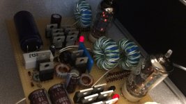
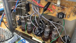
My small Push-Pull amplifier.
Those current meters : Chinese ?
Nice design.My version of push-pull
Those current meters : Chinese ?
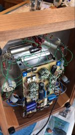
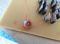
Those handmade chokes : for stability reasons?My small Push-Pull amplifier.
Attachments
The "chokes" are the impedance converters instead of a conventional output transformer. I got this idea from the David Berning website:
Tube amplifiers for high-end audio by The David Berning Company
Tube amplifiers for high-end audio by The David Berning Company
Had a quick look at that website. Interesting indeed but not much info about those "impedance transformers".
Looking at your amp and having a closer look about the amount of windings around the core, I got the feeling
that those inverters do not have much input/output ratio?
Looking at your amp and having a closer look about the amount of windings around the core, I got the feeling
that those inverters do not have much input/output ratio?
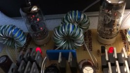
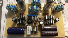
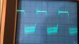
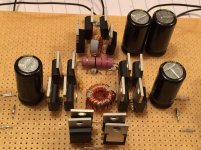
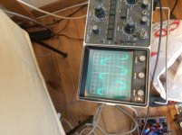
Additional images that can help building this amps. I used common mode choke cores for the transformers. 500Khz oscillator and resonator.
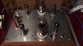
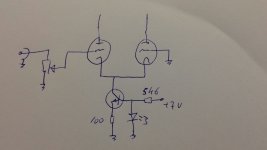
The amp itself is very simple. Some of my amps do not even have a phase inverter as my preamp has a symmetrical output. The "power" tubes are sensitive enough, therefore no driver stage is needed as well.
The amp itself is very simple. Some of my amps do not even have a phase inverter as my preamp has a symmetrical output. The "power" tubes are sensitive enough, therefore no driver stage is needed as well.
Attachments
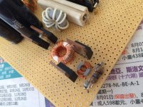
Additional images that can help building this amps. I used common mode choke cores for the transformers. 500Khz oscillator and resonator.
The amp itself is very simple. Some of my amps do not even have a phase inverter as my preamp has a symmetrical output. The "power" tubes are sensitive enough, therefore no driver stage is needed as well.
Thanks Lampie519 for this practical info, much appreciated!
So, if I understand you correctly you are using the diff. amplifier as phase shifter with the transistor as current source?
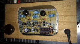
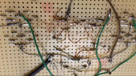
Yes, simple isn't it? That is the entire "power" 1W amp (it can drive my B&W Rock Solids easily).
My advise if someone would like to start this "adventure" : Use a low voltage (max 12V) power supply (short circuit proof).
In this headphone amp i have used a 5V PSU. It can be adjusted to about 7V max.
For this amp it is sufficient.
It is the best Zotl project to start with as it needs no High voltage PSU at all.
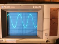
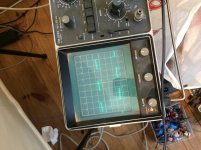
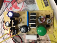
first build a (half) H-bridge and a oscillator. Make sure the square wave form looks good without any harmonics as this would heat up the FET's and could indicate saturation of the ferrite cores. It will burn your FET's in time and the frequency will "run away" causing even more heat dissipation.
Attachments
Yes, simple isn't it? That is the entire "power" 1W amp (it can drive my B&W Rock Solids easily).
My advise if someone would like to start this "adventure" : Use a low voltage (max 12V) power supply (short circuit proof).
In this headphone amp i have used a 5V PSU. It can be adjusted to about 7V max.
For this amp it is sufficient.
It is the best Zotl project to start with as it needs no High voltage PSU at all.
Thanks again lampie519 for this info. The biasing of the current source transistor, I would suggest a resistor in series with the diode to have lesser temperature dependence
of the tail current. Now the tail current increases with increasing ambient temperature (delta Vbe across the 100 Ohm emitter resistor).
I have tried to get an idea what this "zotl impedance converter" is but have to confess that not much data is given here when searching the internet. I have not seen a single schematic so far to
illustrate the idea.
Surely the amp can be improved here and there but to prove the concept it works fine.
The schematic to start with is here (last pages of the manual):
http://davidberning.com/images/microZOTL/microZOTL_Manual.pdf
Tube amplifiers for high-end audio by The David Berning Company
And here:
Tube amplifiers for high-end audio by The David Berning Company
The schematic to start with is here (last pages of the manual):
http://davidberning.com/images/microZOTL/microZOTL_Manual.pdf
Tube amplifiers for high-end audio by The David Berning Company
And here:
Tube amplifiers for high-end audio by The David Berning Company
Last edited:
Surely the amp can be improved here and there but to prove the concept it works fine.
The schematic to start with is here (last pages of the manual):
http://davidberning.com/images/microZOTL/microZOTL_Manual.pdf
Tube amplifiers for high-end audio by The David Berning Company
And here:
Tube amplifiers for high-end audio by The David Berning Company
Ah, that last link is very informative, thanks!
Joe, i will warn you however... once you got a Zotl working you will not be able to stop building more and more as it is extremely addictive !
Joe, i will warn you however... once you got a Zotl working you will not be able to stop building more and more as it is extremely addictive !
🙂 🙂
- Status
- Not open for further replies.
- Home
- Amplifiers
- Tubes / Valves
- Screen driven 6V6 SET a la ZOTL