I'm not doing a screen driven amp, but there are a lot of similarities so I will share my approach.
I thought about choke loading but decided that it was cheaper/easier just to make a regulated +-450V supply with a Hammond 278CX. From that I will derive +-320V as well. My final voltage amplifier would be a 6SN7 CCS loaded (10M90S) with cathode at -320 and B+ at +450V, making 770V. I figured that a 278CX and a few regulators are a lot cheaper than good quality interstage transformers. Plus, the split supply opens up a lot of direct coupling options.
I put a separate power transformer for the power tubes. My target B+ for them is 500V and I spec'd XPWR099 for them, 400V at 1A.
The Edcor XSM series aren't expensive at all. About the same as a new production 6SN7. Or am I off the mark here?
Ok. Time for me to get stoopid. I figure I'll get some decent voltage gain from the 6J6 by itself. A 6CG7 driver stage as-is from the Unverisal schematic can swing some pretty good voltage by itself according to TubeCAD. Just a wee bit less than a 5965. So I'm guessing there's already some pretty good swing going on there, but for the life of me I can't figure out how to calculate the total swing. Any suggested book learning?
I realize I'm going off the ranch with the interstage transformer, but I'm intrigued about how to make it work. From a practical perspective if I can keep the B+ under 500v then my power supply gets cheaper. It would seem that from THIS driver stage voltage swing is important in a screen drive for 6AV5's.
This is all very fascinating. I'll need to draw up something soon.
The Specification for the XSM interstage transformers is 25V RMS.
That's probably not enough for screen drive applications.
it would almost certainly be sufficient for the first stage.
What I was thinking was substituting an Edcor GXPP10-6-10K
for the two 33K plate resistors of the 5965 in the screen drive schematic you linked to. The secondaries would be open. B+ would have to be modified (lowered) to keep the plate voltage in spec.
An inductor load does not allow for larger maximum swing, it allows for a lower power supply voltage for the same swing compared to an active load or a resistor.
Total voltage gain is the stage gains multiplied. I use Tube Cad to approximate Av for each stage. Assume 2 V RMS input.
Doug
Doug, I'm from Aurora, IL. Good times out there, but haven't been back in a long time.
Thanks for the reality check. I think it will be difficult to find a transformer that can swing it, but the anode load is something I hadn't thought about. Good tip.
Thanks for the reality check. I think it will be difficult to find a transformer that can swing it, but the anode load is something I hadn't thought about. Good tip.
Right around the courner.Doug, I'm from Aurora, IL. Good times out there, but haven't been back in a long time.
Doug
Let's say I've lost my mind and I was going to custom build an interstage transformer for the output of the driver stage.
B+ is set to 450v which puts a mathematical 274v on the 6CG7 anode. Bias current is set to 10ma. Vout is 183v pk-pk theoretically. The Z out would be about 19k so I would expect a 15k primary on the transformer to be reasonable. Playing with the secondary winding could affect the Vout from the transformer if I'm not mistaken. What would the ma rating need to be? My wild guess is 250ma?
Let's say I go nuts, B+ goes to 500v, and the anode sees 321v. Swing starts looking like a possible 223v pk-pk. 359ma?
This was an interesting read: http://www.vias.org/eltransformers/lee_electronic_transformers_06_15_03.html
Very interesting topic!
http://www.diyaudio.com/forums/showthread.php?s=&threadid=132552&perpage=25&pagenumber=1
http://www.diyaudio.com/forums/showthread.php?s=&threadid=132552&perpage=25&pagenumber=1
"The Specification for the XSM interstage transformers is 25V RMS."
Where do you get such a low voltage?
Watts = Vrms*Vrms/R and Vpk = 1.414 * Vrms
For Edcor XSM15K/15K:
2.5 = Vrms*Vrms/15000 -> Vrms = 193.6 Volt or Vpk to pk = 273.8 V
DC resistance of the 15K windings is about 2 K Ohm end to end however, so there will be some voltage drop internally depending on screen current drawn unless a Mosfet follower is used.
The XSM 15K/15K I have measures 52 nF from primary to secondary, so these seem to be bifilar wound. Not a limitation if the Pri and Sec center taps are both grounded AC wise. But this eliminates connecting the Pri and Sec windings in series for higher Z autoxmfr use.
I did get a response from a transformer manufacturer that transformers are rated by current not voltage. This makes sense to me.
The Mosfets should be providing the current, so the driver stage should be providing the V pk-pk. I wouldn't expect a whole lot of current out of a 6CG7, even on a good day, so I would expect the XSM to be fine. Some of the fancier transformers are rated at 200ma and look like output transformers.
It would seem to get a bump in the swing a ratio of at least 1:1 is needed, 1:1.2 even better.
Please ignore my weird calculating from earlier.
Looking Again, I do not see that either. I thought I saw it on the old site."The Specification for the XSM interstage transformers is 25V RMS
Sorry for the detour.
I know there is a max flux density, but it would be current, not voltage.
Carry on.
Doug
Ok. Spending some time on Upgrade Island has cooled me off to the whole interstage transformer thing. I do intend to go off the ranch though. New idea.
6J6 --> Triode strapped 7W7's --> 2SK2700 (x4?) --> *AV5 (x4)
No tubes that cost more than a buck.
With PPP on the output I shouldn't need as much swing to get up to the OPT's 100w rating.
P.S. I notice that Antek has a new series of OPT's with a lot more taps on the primary and secondary. I apparently got the surplus older model, but it's good for this project.
Some related interesting reading: http://www.audiokarma.org/forums/showthread.php?t=151142
Some related interesting reading:
I don't have an audiokarma login so I can't see the schematics.
With PPP on the output I shouldn't need as much swing to get up to the OPT's 100w rating.
You have a 2022 ohm CT primary. To get 100 watts RMS you will need 635 volts P-P at each plate. This is ohms law regardless of how many tubes and what kind they are. Ohm will aslo tell us that the peak current will be about 1.25 AMPS, a bit much for one 6AV5, so two per side is about right.
I started out to build a big power screen driven amp to make use of the 400 watt Plitron toroidal OPT's that I got. The "universal driver board" was to be used to drive it. Another poster got me interested in morphing that board into a direct coupled driver that would be capable of driving a pair of 6L6GC's up to 30 watts or so. So now I have a driver board that uses a pair of 6SN7's and a pair of mosfets. I have connected it up to a bunch of different tubes just to see what would happen. I have extracted over 100 watts from a pair of 6L6GC without any glow using AB2. I have not tested to see if that board will put out enough drive voltage for screen drive. I belive that it will be OK.
I was testing several tubes and I tried the Electro Harmonix KT88 in triode mode. This sounded real nice and produced about 75 watts. I found some old WWII surplus tubes that looked cool. I managed to find 2 good ones, saw them crank out 100 watts in triode, and heard some magic coming out of my speakers. I am fixated on this design right now, so screen drive is on hold.
...screen drive is on hold.
No hurries, no worries.
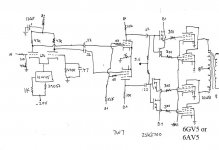
So I whooped up a schematic for entertainment sake. Half baked, but you get where I'm going with this. It's sort of a chimera of the Tubelab Universal and the PMillett 307a PP.
A photo of the current cast and crew is below too.
Attachments

So I whooped up a schematic for entertainment sake. Half baked, but you get where I'm going with this. It's sort of a chimera of the Tubelab Universal and the PMillett 307a PP.
I'll be watching your project with interest. I have a small stash of 6JM6's here, which coincidentally appear to be virtually identical to your 6GV5's, except for some of the internal connections.
Jeff
I have to admit I have an alternate motive for this amp. I'm looking resurrect my bass playing and it would be fantastic if I had 2 x 100w driving my SWR cabs. I've got a nicely insulated basement so I can get loud. The Alembic needs action folks.
I've got a DI box that can provide the gain needed. I've never cared for tone controls. I can control tone with playing style.
I've got a DI box that can provide the gain needed. I've never cared for tone controls. I can control tone with playing style.
It's time to build this puppy just for my own amusement. I'm going to do just one channel first. I'll keep it simple by trying to stay as close to the original schematic at first and then I'll tweak.
Tubelab if you're reading, what kind of 20k 5w resistor did you use on the screens? Wirewound (inductive/non-inductive), MOX, film?
For the pots, I would guess that 1/2w is sane?
Tubelab if you're reading, what kind of 20k 5w resistor did you use on the screens? Wirewound (inductive/non-inductive), MOX, film?
For the pots, I would guess that 1/2w is sane?
Last edited:
So, you screen drive guys find optimum G1 at cathode potential?
Or do you prefer G1 with a sand diode's drop above or below the cathode?
How high can you take G1 without ruining the G2 protective effect of its shadow?
Or do you prefer G1 with a sand diode's drop above or below the cathode?
How high can you take G1 without ruining the G2 protective effect of its shadow?
Last edited:
Tubelab if you're reading, what kind of 20k 5w resistor did you use on the screens?
You mean the resistors that are missing from your schematic (SG to ground or negative supply). I have used whetever that I had laying around. My latest experiments have been using some 10K 6.5 watt WW resistors that I got for Tubelab SE amps. I have also used the white Xicons that I use in the Simple SE, but they are hard to find in 20K (although I have some in another brand) I have also used some 20K 3 watt MOX parts from Mouser. All work good.
For the pots, again I used whatever I could find, mostly leftovers from Tubelab SE amps. The issue with most pots are their maximum voltage rating. I usually use additional resistors on each end of the pot to lower the voltage across the pot. I have been running the mosfets on a lower supply voltage to keep their dissipation down. You need resistors from grid to ground on the 7W7's. I'm just guessing, maybe 470K. Put a 10 ohm in the cathode of each output tube so you can measure the cathode current.
So, you screen drive guys find optimum G1 at cathode potential?
That has been the accepted norm, but my findings dont exactly concur. I find that a slight negative bias can improve distortion especially at low currents. Increasing the negative bias improves the distortion but causes another problem. More negative bias means more positive screen voltage is required to get the same tube current. At high power output levels, on positive signal peaks, the screen grig voltage will be high (maybe 250 volts) while the plate voltage will be very low. This is the recipie for a melted screen grid (or worse). Actually this isn't much of a problem with normal music, but it led to a nuclear event inside a 6BQ6 as I was extracting 100+ continuous watts out of a pair. There is a happy medium here and it sems to vary with tube type, but I haven't had the time to experiment lately.
This thread has become something more like a blog. Regardless:
I thought this was an interesting read. It kinda follows what I was thinking with the inter stage transformer, except it uses a chip amp to drive the output stage. I'm not going in that direction, but it's something to think about.
I also found another matching big Tek power transformer cheap. Monoblocks.
I've been trying to put the wraps on a couple outstanding projects before diving into this one. Along the way I've discovered the likes of the 6HV5's and friends. Very interesting tube, but it would need at least 900v. Could it be both driver and output? Some experimentation is needed.
Along the way I've discovered the likes of the 6HV5's and friends.
The 6HV5 has a lot of friends including the 6JD5 which is on the $1 list at ESRC. I have used it in a very simple true spud amp. Just the tube, an OPT and a power supply. No it didn't work very well and yes it takes a lot of voltage to get it to work.
These tubes have a Mu of 300. This makes them a better 811A than the 811A is. The 811A has some well known drawbacks like a high plate resistance, and the need to run in A2 for any reasonable plate voltage. In spite of these drawbacks there have been some well regarded amplifiers made with them. I would assume that the same techniques used with the 811A could be used with the 6HV5 family.
The high plate resistance almost guarantees the use of some type of feedback to lower the output impedance. After spending some time with the red board I have a new respect for schade type feedback. It makes a pentode output stage work like a triode. Will it make a triode look like a better triode?
It is safe to assume that these tubes wont be on the dollar menu once someone figures it out.
- Status
- Not open for further replies.
- Home
- Amplifiers
- Tubes / Valves
- Screen Drive Push Pull ideas