Split from 6JN6 screen-drive (g2 driven) plate curves?
Hello, the voltage current transfer curve of a tube driven at a negative grid is non linear. The usual way to minimize the distortions caused by this non linearity is neagtive feedback and/or compensation of this non linearity, e.g. push pull. These methodes are used in solid state devices too. Thus the result is not much different. If you don't want these usual linearisation methods there is another option. The triode. It makes a self linearisation caused by the influence of the anode voltage in the electric field between cathode and grid. Same takes place in the so called "Ultralinear Circuit". It is the change of the g2 voltage that makes this influence. A positive grid ideally eliminates the influence of the following electrodes in the electric field surrounding the cathode. Thus a triode with positive grid voltage is getting more and more pentode like, the positiver the grid is. A pentode (and tetrode) driven at g2 is still a pentode because the g2 is positive and eliminates the influence of the anode in the electric field between cathode and g1. Thus the name "enhanced triode mode" is wrong here. There is a strong similarity between a bipolar transistor and a pentode driven at g2 and you can say it is a pentode in the bipolar mode. #16 All applications I have seen suffer with the problem that the voltage to current conversation at the positive g2 is still non linear. Some people accept this nonlinearity😉 and reduce it in the usual way as explained at the beginning. You can see this non linearity in the change of the spacing of the horizintal output curves of the pentode .#6 It is possible to make the g2 voltage drive linear and the spacing equal. #21 I'll explain this in the next post.🙂
Kind regards, Darius
getting linear voltage drive at g2 of a pentode...
Good evening, the interesting question is: Where does this non linearity come from? In an ideal pentode the ratio between g2 and anode is fixt similar to the hfe of a bipolar transistor. The anode current is set by the g2 current like the collector current is set by the base current. The g2 current is set by the characteristic of the triode section (cathode g1 and g2=anode triode) of the pentode. In a bipolar transistor it is the base emitter diode. The output curve of the base emitter diode is non linear. Adding a resistor in series with this diode makes it more linear. #13 The output curves of a triode at negativ grid voltages is diode like and this causes the non linearity in the voltage current transfer of the triode section in a pentode. Now comes the solution: At negative grid voltages a triode output is diode like. At 0V it is still diode like. But at positive grid voltages the curves are getting more and more horizontal. The triode's anode looses the influence in the electric field between grid and cathode. Between these, the triode's output curve is linear like a resistor. This makes it possible to drive the triode section at its anode=g2 of the pentode linear. A little positive voltage at g1 of the pentode makes the g2 drive very linear. The spacing of pentode's output curves is equal now. 🙂 #7 The g1 voltage makes the spacing adjusable. I tried it out at an EL84 this morning and the result is excellent! I am happy.
Comments?
Kind regards, Darius
Hmmm, very interesting.
After you mentioned that you had another way to linearize g2 drive in the other thread, I thought about this for a while. I eventually came to a similar conclusion that positive g1 should at least be checked out, but for somewhat different reasons. Mainly I concluded that the processes in g2 drive were a bit too complicated to model in simple theory, and needed a workbench model to tweek some variables while watching a curve tracer. Have you seen this result on a curve tracer?
My first linearization guess was to just put a resistor in the cathode circuit, similar to emitter degeneration for SS. This probably can help, but is a bit lossy for power outputs.
As I had already mentioned the scheme of putting some small resistance in the g2 drive to balance screen current distortion against 3/2 power distortion, I then considered some ways to improve the g2 current linearity since it tends to have a bad kink in its curve.
1st, I should maybe explain the idea of g2 "hfe" for those tuning in recently. Through much of the operating range of a pentode the g2 (screen) intercepts a relatively constant fraction of cathode current simply by mechanical cross-sectional collision of the electron beam.
This perhaps has led to the idea in some quarters of a constant "hfe" or "beta" as in a bipolar transistor model when using g2 drive. (the bipolar model would really be a bit more appropriate I think for a class A2 positive g1 drive, but in g2 we just have much lower transconductance, gm, so voltage swings on g2 are much larger)
When the plate voltage drops down to near or below the screen potential however, the screen begins to absorb significantly more current than just its mechanical cross-section. Causing a big droop in the "hfe" or "beta" effectively. (somewhat similarly to poor bipolar parts) Some of this is due to the return field between screen and plate.
An additional factor in the increased screen current is the progressive failure of the focusing due to the g1 aligned grid wires (at least for tubes that have them) of the eletron beam to miss the screen wires.
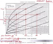
So, with this in mind, I first considered the most obvious approach to "fixing" the g2 current as to just put some negative bias on the g1 grid so as to bring back some focusing effect. But after looking at the g1 data curves for the 6JN6 in post 2 (other thread)
http://www.diyaudio.com/forums/showthread.php?postid=1478837#post1478837
it becomes apparent that g1 focussing "failure" is what puts the kink in the screen current curves. Less g1 neg. bias looks less kinked. Unfortunately the curves do not cover positive g1 bias. But my guess is that a small positive bias on g1 actually causes the g1 focussing effect to mis-focus the cathode beam right onto the g2 wires at low cathode current. As the cathode current rises, this g1 focusing onto g2 wires begins to fail due to the other fields becoming so much stronger than the tiny g1 field, so screen interception with focussing failure actually counters the usual trend of greater g2 current as plate voltage decreases. As you similarly observed the plate curves themselves straightening out for small positve g1.
It may still be useful, even with positve g1, to put some small resistance in the g2 drive to counteract 3/2 power distortion of plate current. And of course, saturation effects are an uncompensated effect still.
So your finding of positive g1 bias for linearization is an interesting one in any case (regardless as to how to explain it). Probably many other 2nd order effects are going on as well.
It would seem a comprehensive experiment is called for to explore g2 drive linearity, with variable g2 drive resistance, variable g1 bias, variable cathode resistor, and variable load resistance. And either a curve tracer or FFT to observe the results. Getting an FFT clean g2 drive test signal level though will be somewhat problematic.
Don
After you mentioned that you had another way to linearize g2 drive in the other thread, I thought about this for a while. I eventually came to a similar conclusion that positive g1 should at least be checked out, but for somewhat different reasons. Mainly I concluded that the processes in g2 drive were a bit too complicated to model in simple theory, and needed a workbench model to tweek some variables while watching a curve tracer. Have you seen this result on a curve tracer?
My first linearization guess was to just put a resistor in the cathode circuit, similar to emitter degeneration for SS. This probably can help, but is a bit lossy for power outputs.
As I had already mentioned the scheme of putting some small resistance in the g2 drive to balance screen current distortion against 3/2 power distortion, I then considered some ways to improve the g2 current linearity since it tends to have a bad kink in its curve.
1st, I should maybe explain the idea of g2 "hfe" for those tuning in recently. Through much of the operating range of a pentode the g2 (screen) intercepts a relatively constant fraction of cathode current simply by mechanical cross-sectional collision of the electron beam.
This perhaps has led to the idea in some quarters of a constant "hfe" or "beta" as in a bipolar transistor model when using g2 drive. (the bipolar model would really be a bit more appropriate I think for a class A2 positive g1 drive, but in g2 we just have much lower transconductance, gm, so voltage swings on g2 are much larger)
When the plate voltage drops down to near or below the screen potential however, the screen begins to absorb significantly more current than just its mechanical cross-section. Causing a big droop in the "hfe" or "beta" effectively. (somewhat similarly to poor bipolar parts) Some of this is due to the return field between screen and plate.
An additional factor in the increased screen current is the progressive failure of the focusing due to the g1 aligned grid wires (at least for tubes that have them) of the eletron beam to miss the screen wires.
So, with this in mind, I first considered the most obvious approach to "fixing" the g2 current as to just put some negative bias on the g1 grid so as to bring back some focusing effect. But after looking at the g1 data curves for the 6JN6 in post 2 (other thread)
http://www.diyaudio.com/forums/showthread.php?postid=1478837#post1478837
it becomes apparent that g1 focussing "failure" is what puts the kink in the screen current curves. Less g1 neg. bias looks less kinked. Unfortunately the curves do not cover positive g1 bias. But my guess is that a small positive bias on g1 actually causes the g1 focussing effect to mis-focus the cathode beam right onto the g2 wires at low cathode current. As the cathode current rises, this g1 focusing onto g2 wires begins to fail due to the other fields becoming so much stronger than the tiny g1 field, so screen interception with focussing failure actually counters the usual trend of greater g2 current as plate voltage decreases. As you similarly observed the plate curves themselves straightening out for small positve g1.
It may still be useful, even with positve g1, to put some small resistance in the g2 drive to counteract 3/2 power distortion of plate current. And of course, saturation effects are an uncompensated effect still.
So your finding of positive g1 bias for linearization is an interesting one in any case (regardless as to how to explain it). Probably many other 2nd order effects are going on as well.
It would seem a comprehensive experiment is called for to explore g2 drive linearity, with variable g2 drive resistance, variable g1 bias, variable cathode resistor, and variable load resistance. And either a curve tracer or FFT to observe the results. Getting an FFT clean g2 drive test signal level though will be somewhat problematic.
Don
Another effect on cathode current from a positive g1 bias would be the current draw by g1 itself. Probably is a larger percentage at smaller cathode currents, but I'm not sure about that. But it brings up another way to influence overall linearity. A series resistor between g1 and the positive bias supply might be useful. Let's see, how many variables do we have now....
Don
Don
Hi Darius,
What do you mean with the term "ideally" in this context?
That´s nonsense. Plate curves for arbitrary triodes with the control grid driven positive certainly don´t look pentode-like except they get a "knee", but the significant coefficients like mu, ra and gm stay very constant for any practical usage range circumstances - just have a look at them, f.e 6SN7, scroll to page 4.
If your argumentation is aiming at pentode virtues like extremely low Ca-g due to confining the space charge area between cathode and the control grid at a lower (but positive) Eg1 than Ea, this argument is moot for any triode w/ g1 driven positive because you need much more power to drive the control grid than to overcome _any_ Cin (CMiller) whatsoever - the power needed to drive Cin to freqs desired simply gets swamped by the power need to drive the control grid positive (or even just holding the control grid positive).
That is why real tetrodes, BPTs and pentodes are "the preferred solution" for the "problem" you are adressing, but not triodes w/ control grid held at positive voltage level.
Regards,
Tom
oldeurope said:Split from http://www.diyaudio.com/forums/showthread.php?s=&threadid=120969
A positive grid ideally eliminates the influence of the following
electrodes in the electric field surrounding the cathode.
What do you mean with the term "ideally" in this context?
Thus a triode with positive grid voltage is getting more and more pentode like, the positiver the grid is.
That´s nonsense. Plate curves for arbitrary triodes with the control grid driven positive certainly don´t look pentode-like except they get a "knee", but the significant coefficients like mu, ra and gm stay very constant for any practical usage range circumstances - just have a look at them, f.e 6SN7, scroll to page 4.
If your argumentation is aiming at pentode virtues like extremely low Ca-g due to confining the space charge area between cathode and the control grid at a lower (but positive) Eg1 than Ea, this argument is moot for any triode w/ g1 driven positive because you need much more power to drive the control grid than to overcome _any_ Cin (CMiller) whatsoever - the power needed to drive Cin to freqs desired simply gets swamped by the power need to drive the control grid positive (or even just holding the control grid positive).
That is why real tetrodes, BPTs and pentodes are "the preferred solution" for the "problem" you are adressing, but not triodes w/ control grid held at positive voltage level.
Regards,
Tom
#3 #4
Hello Don,
I picked up the g2 voltage at 20mA, 40mA and 60mA anode current at 250V anode voltage.
I got the smallest transconduction change at +300mV at g1(g1 current is 240µA).
I agree with you that there are other effects too. But there is definitely a g1 voltage
that provides best linearity.
The resistor in the cathode (emitter, source) circuit is current feedback and makes it linear
(if there is a signal voltage drop at this resistor).
It is one of the usual negative feedback methods.
Kind regards,
Darius 🙂
#5
Hello Tom,
I mean that the following electrodes are not able to change the cathode current.
Nonsense? 😕 The curves in page 4 are pentode (transistor) like at positive grid voltages!
Thanks for the example.😀
Kind regards,
Darius
Hello Tom,
I mean that the following electrodes are not able to change the cathode current.
Nonsense? 😕 The curves in page 4 are pentode (transistor) like at positive grid voltages!
Thanks for the example.😀
Kind regards,
Darius
Looking at the 6SN7GTB curves, page 4 top, we could call the plate voltage axis the g2 voltage axis for our pentode (assuming the actual pentode plate V does not have much effect on the current for the moment). The plate current axis would be our g2+plate current for the pentode. Operation would be along a +300mV char. curve.
Comparing this with the page 4 bottom char. curves (negative g1), it does look like the (+g1) char. curves are straightened out considerably, so the g2 now appears to be having a more linear affect. But I don't think you can say that a positive electrode prevents outer electrodes from having any influence, otherwise the curve would be horizontal. (and the spacing betweent the 6SN7 curves for +g1 would be constant too, which clearly are not)
The screen current however has not been accounted for, and would still be increasing dramatically as the real pentode plate voltage drops. So the pent. plate current "hfe" will likely still droop
at large signal.
If we were to drive the g2 with a HV Mosfet follower, and return its drain current to the pentode plate terminal, then the g2 current partition issue would be avoided. So we would be left with a fairly linear g2 voltage to pent. plate current transfer (ie, constant gm2 effectively).
Next problem to solve I think would be the high output Z of the tube. g2 drive is still giving a pentode like Zout. I wonder if the small positive voltage on g1 were derived from a resistive divider from the pent. plate, if this would be sufficient to lower output Z and not disturb the linearity correction. Who knows, maybe it works even better, since the neg. g1 fdbk should be linearizing.
Don
Hello Don,
Kind regards, Darius 🙂
You forget the word ideally. (Please read post #1) BTW: This is the basic function of a screen grid. A positive grid ideally prevents outer electrodes from having any influence in the cathode current. A negative grid does not. This is why a triode with negative grid voltages has diode like output curves.Originally #8 posted by smoking-amp But I don't think you can say that a positive electrode prevents outer electrodes from having any influence, otherwise the curve would be horizontal.
Hm, I think this is desired in a grounded cathode pentode amp. 😎 If you don't like it change the topology (e.g. cathode follower) or take a triode to get a low Z output. No negative feedback and semiconductors please. 😉 I agree with the rest of your post.Originally #8 posted by smoking-amp ...Next problem to solve I think would be the high output Z of the tube. g2 drive is still giving a pentode like Zout. ...
Kind regards, Darius 🙂Re: #5
Hi Darius,
Gee, don´t let yourself get fooled by the scale. The curves shown (and their spacings) are just sequels (except for the knee) of the ones "on the other side" of Eg=0V, means Eg1 being held negative.
Please have a closer look, and if still in doubt, please just compute mu, gm and ra at some points and you will understand that what you see has nothing to do with pentode behaviour (like extremely high plate resistance and mu). They are not too far from just normal / standard operation coefficients of type 6SN7.
Regards,
Tom
Hi Darius,
Nonsense? 😕 The curves in page 4 are pentode (transistor) like at positive grid voltages!
Thanks for the example.😀
Gee, don´t let yourself get fooled by the scale. The curves shown (and their spacings) are just sequels (except for the knee) of the ones "on the other side" of Eg=0V, means Eg1 being held negative.
Please have a closer look, and if still in doubt, please just compute mu, gm and ra at some points and you will understand that what you see has nothing to do with pentode behaviour (like extremely high plate resistance and mu). They are not too far from just normal / standard operation coefficients of type 6SN7.
Regards,
Tom
Hi Darius,
please notice that the curves for positive Eg values are just in parallel to those of Eg = 0, -5 and -10 Volt respectively, so at least for the straight parts, the three determining coefficients mu, gm and ra coefficients have the same values as with normal (negative) g1 operation, for all practical purposes.
IOW, what you see is, that 6SN7 simply keeps its linear mu _and_ linear gm behaviour also when g1 is held positive. Hence no plate resistance anomalies, either.
So, yes, I still think your argumentation chain is nonsense, because the premise you made it is based on a wrong assumption.
Regards,
Tom
very nice disscusion here....😀
keep it going guys, and SY, can we make this thread a sticky to address all G2 drive dicussion issues please?
thanks you.....
keep it going guys, and SY, can we make this thread a sticky to address all G2 drive dicussion issues please?
thanks you.....
Sorry I couldn't take the time to read the details. But it seems like you are describing space charge operation (G2 driven, G1 biased positive relative to cathode). If so, this is how they got tubes to run off 12V for automotive back in the day.
#5 #10 #11
Hi Tom, hope this graph helps understanding. Output curve 1 shows a linear resistor. Curve 2 shows a diode or a triode at negative grid voltages. Curve 3 shows a pentode, tetrode etc., transistor FET BJT or a triode at positive grid voltages. You can adjust the output curve of a triode from diode to transistor by adjusting the grid voltage. Ideally curve 3 is horizontally and starts at 0V. 😉 Kind regards, Darius
Hi Tom, hope this graph helps understanding. Output curve 1 shows a linear resistor. Curve 2 shows a diode or a triode at negative grid voltages. Curve 3 shows a pentode, tetrode etc., transistor FET BJT or a triode at positive grid voltages. You can adjust the output curve of a triode from diode to transistor by adjusting the grid voltage. Ideally curve 3 is horizontally and starts at 0V. 😉 Kind regards, Darius
Attachments

#14
D.
Please read post #2 and #8. 😉Originally #14 posted by Jeb-D.
Sorry I couldn't take the time to read the details. ...
D.
#15
http://frank.pocnet.net/index.html
Here are the output curves of the AL1 pentode
and the 811A Triode positive grid.
Kind regards,
Darius
http://frank.pocnet.net/index.html
Here are the output curves of the AL1 pentode
and the 811A Triode positive grid.
Kind regards,
Darius
Attachments
Re: #5 #10 #11
Hi Darius,
Okay, the curves may look "pentode-like", but that is just optics, because neither with a pentode nor with a triode having g1 driven positive you want to come anywhere near the "knee" for a practical operation point. But chosing a practical op point for a triode w/ g1 positive - still using 6SN7 as an example - you still will get triode-like coefficients for mu, gm and rp, see attachment.
Actually, you get:
µ = 15
gm = 3,75mA/V
rp = 4 kOhm
over a wide range, which is quite close (factor less than 2) to 6SN7 coefficients at standard (negative g1) operation. Now compare this to any real "pentode like" coefficients.
Again, my points is: The curves may look pentode-like, but don´t get fooled by scaling. For any _practical_ purpose you still get triode-like _coefficients_ when driving g1 of a triode positive, and _that_ is what counts, but not misleading optics by changed scales.
Now please fix your signature in this regard, which is needlessly provoking.
Regards,
Tom
Hi Darius,
oldeurope said:Hi Tom,
hope this graph helps understanding.
Output curve 1 shows a linear resistor.
Curve 2 shows a diode or a triode at negative grid voltages.
Curve 3 shows a pentode, tetrode etc., transistor FET BJT or a triode at positive grid voltages.
You can adjust the output curve of a triode from diode to
transistor by adjusting the grid voltage.
Ideally curve 3 is horizontally and starts at 0V. 😉
Kind regards,
Darius
Okay, the curves may look "pentode-like", but that is just optics, because neither with a pentode nor with a triode having g1 driven positive you want to come anywhere near the "knee" for a practical operation point. But chosing a practical op point for a triode w/ g1 positive - still using 6SN7 as an example - you still will get triode-like coefficients for mu, gm and rp, see attachment.
Actually, you get:
µ = 15
gm = 3,75mA/V
rp = 4 kOhm
over a wide range, which is quite close (factor less than 2) to 6SN7 coefficients at standard (negative g1) operation. Now compare this to any real "pentode like" coefficients.
Again, my points is: The curves may look pentode-like, but don´t get fooled by scaling. For any _practical_ purpose you still get triode-like _coefficients_ when driving g1 of a triode positive, and _that_ is what counts, but not misleading optics by changed scales.
Now please fix your signature in this regard, which is needlessly provoking.
Regards,
Tom
Attachments
funny...
Hi Tom,
it is not just optics, it is mathematics.
"Resistor like" means differential and static resistance
do not change with the voltage, see Curve 1.
"Transistor like" means differential resistance increases
at increasing DC- voltages, see curve 3.
"Triode like" means differential resistance decreases
at increasing DC- voltages, see curve 2.
Tom, you are a funny guy.😉
You are telling in other words what I wrote in my signature, hi hi.
Technical forum rules:
µ = hfe_ hie = 1/hoe_ triodes don't change their characteristic at positiv grid voltages _ anode current is independent from g2 current in a pentode_ calculating the gain of a triode cathode follower you have to ignore the influence of µ_ ignore Loftin White_ ignore the fourth circuit topology_ tubes should be replaced by mosfets_ neutralisation is forbidden_ continued ... 😉
I don't like these rules, I have to accept them here in the forum.
Kind regards,
Darius
Hi Tom,
Originally #18 posted by Tubes4e4
Hi Darius,
Okay, the curves may look "pentode-like", but that is just optics,
...
Tom
it is not just optics,
it is mathematics."Resistor like" means differential and static resistance
do not change with the voltage, see Curve 1.
"Transistor like" means differential resistance increases
at increasing DC- voltages, see curve 3.
"Triode like" means differential resistance decreases
at increasing DC- voltages, see curve 2.
Originally #18 posted by Tubes4e4
Hi Darius,
...
Again ... you still get triode-like _coefficients_ when driving g1 of a triode positive,...
Now please fix your signature in this regard, which is needlessly provoking.
Regards,
Tom
Tom, you are a funny guy.😉
You are telling in other words what I wrote in my signature, hi hi.
Technical forum rules:
µ = hfe_ hie = 1/hoe_ triodes don't change their characteristic at positiv grid voltages _ anode current is independent from g2 current in a pentode_ calculating the gain of a triode cathode follower you have to ignore the influence of µ_ ignore Loftin White_ ignore the fourth circuit topology_ tubes should be replaced by mosfets_ neutralisation is forbidden_ continued ... 😉
I don't like these rules, I have to accept them here in the forum.
Kind regards,
Darius
Re: Re: #5 #10 #11
Anyway, the way I see it is, oldeurope is saying that at some G1 voltage which is more positive than 0V, you will find a point where the grid curve is very neary linear (resistive).
This is of limited use in a real triode, but a pentode/tetrode has the screen grid to play with. Therefore you could fix the G1 voltage at the 'ideal' positive value, and input the audio signal to G2 instead (which would be referenced to ground). The valve can therefore operate over a nearly linear transfer characteristic.
Mu at the screen grid is very low of course, so what you gain in linearity you lose in input sensitivity- nothing for nothing.
Or have I got this all wrong?
I think there may be some misunderstanding on both parts here, or maybe I'm the one not understanding (sorry oldeurope, but the language barrier is always tricky in scientific circles!).Tubes4e4 said:Hi Darius,
Okay, the curves may look "pentode-like", but that is just optics, because neither with a pentode nor with a triode having g1 driven positive you want to come anywhere near the "knee" for a practical operation point. But chosing a practical op point for a triode w/ g1 positive - still using 6SN7 as an example - you still will get triode-like coefficients for mu, gm and rp, see attachment.
Anyway, the way I see it is, oldeurope is saying that at some G1 voltage which is more positive than 0V, you will find a point where the grid curve is very neary linear (resistive).
This is of limited use in a real triode, but a pentode/tetrode has the screen grid to play with. Therefore you could fix the G1 voltage at the 'ideal' positive value, and input the audio signal to G2 instead (which would be referenced to ground). The valve can therefore operate over a nearly linear transfer characteristic.
Mu at the screen grid is very low of course, so what you gain in linearity you lose in input sensitivity- nothing for nothing.
Or have I got this all wrong?
- Home
- Amplifiers
- Tubes / Valves
- screen-drive (g2 driven) plate curves spacing linear!