Finally after 3 months of braving the 90's temps, 95% humidity, and endless cloudless skys of Illinois this summer I found a couple nice amps at an auction today.
Sadly they arent exactly identical. A Scott 99B and a 99C.
I actually talked with the original owner at the auction today. He said back when he bought them, He bought to 99B and by the time he could aford the second amp, The 99C was out. Both units were fully functional when he retired them.
His claim was they were basically the same just a couple lamp and knob differences.
Anyway, I have the 99B chassis out to clean as its surely going to need no less than a good looking over.
Very Impressive point to point wiring, And more impressive, The Quality componets of the era,
Chassis Underside
The chassis's arent especially dirty as shown here you can see I only gave it a quick wipe before this photo.
Chassis Top View
Anyway, If anyone has info on these units, I would love to find out everything I can on them. Possibly a website or someplace that has even any specs.
These units have 2-6L6's 3-12AX7's, And a 5U4. Speaker outs for 4-8-16 ohm, And a bunch of input options.
I'll get more photos later tomorrow as I only just got home with these 1 hour ago.
Gene
The 99B and 99C are covered in the same Sams Photofact folder - #370-11 from 1957. I don't think I have that one, but many online sellers will have it.
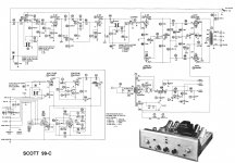
Schematic online at http://www.hhscott.com/pdf/99B.pdf
Schematic online at http://www.hhscott.com/pdf/99B.pdf
Thanks Tom,
I found a free site(donations accepted) Covering the schematics on these.
HS Scott Stereo archives
Sadly, One of these has a dead 5V filament winding, Or lets say the wire coming from the transformer is so brittle and crumbling when flexed it falls apart) Most likely shorted as a result.
The sort of working unit is going to be a tuffy to figure out though it does omit some sound.
Acording to that website, 22W opt, Mono Integrated "Transcription" Amplifier 1954-1956 $99.00 original price tag WOW, thats like 14,000 today right?? lol
Thanks!
Gene
Inflation is about 5x from 1957 to today, so about $500 per channel...
The bad 5V winding can be handled with a pair of 1KV diodes as rectifier (fast recovery type are best) and a 200 Ohm or so 10W resistor to drop the excess voltage. The alternative is to find a transfomer that will fit (may be hard) or an original Scott (well nigh impossible).
The bad 5V winding can be handled with a pair of 1KV diodes as rectifier (fast recovery type are best) and a 200 Ohm or so 10W resistor to drop the excess voltage. The alternative is to find a transfomer that will fit (may be hard) or an original Scott (well nigh impossible).
Is this a weird cathode bias setup or what? The cathode voltage off the 6L6's feeds the center tap of the 6.3 volt winding and the heaters in series of v2 V3 unless I am mistaken. If I am reading the schematic correctly the 6L6 cathode voltage is 20 volts and this feeds the two 12.6 heaters of V2 and V3.
So what happens when the cathode voltage goes higher than 20 volts say 39 volts? If I am seeing this correctly then a voltage adjustment is needed for the heaters of V2 and V3, right?
I'm only getting about 10 watts out of this amp. Isn't is supposed to be 20 watts?
So what happens when the cathode voltage goes higher than 20 volts say 39 volts? If I am seeing this correctly then a voltage adjustment is needed for the heaters of V2 and V3, right?
I'm only getting about 10 watts out of this amp. Isn't is supposed to be 20 watts?
Attachments
Last edited:
So what happens when the cathode voltage goes higher than 20 volts say 39 volts?
Why would it go from 20 to 39V?
Quote:
Why would it go from 20 to 39V?
Output tubes changed? I got it with bad metal 6L6's in it and I put in what I had and that was two 6L6GC'c.
The bias resistor that was supposed to be 3K was to give 20 volts across it. The bias resistor actually measured 2.7K I got 39 volts with the tubes warmed up fully.
Last edited:
It's not the 3k resistor that's biasing the tubes. That resistor only draws 7mA at 20V.
The 2 filaments in series are the actual cathode resistor. They draw 150mA at 20V, establishing the quiescent of 75mA per 6L6.
At 39V, the filaments would have to draw roughly 300mA and that would burn out the filaments AND blow up the 6L6s.
I suspect you disconnected the series filaments from the 6L6 cathodes. Put them back the way Mr. Scott intended and everything will be OK")
The 2 filaments in series are the actual cathode resistor. They draw 150mA at 20V, establishing the quiescent of 75mA per 6L6.
At 39V, the filaments would have to draw roughly 300mA and that would burn out the filaments AND blow up the 6L6s.
I suspect you disconnected the series filaments from the 6L6 cathodes. Put them back the way Mr. Scott intended and everything will be OK
quote:
The 2 filaments in series are the actual cathode resistor. They draw 150mA at 20V, establishing the quiescent of 75mA per 6L6.
At 39V, the filaments would have to draw roughly 300mA and that would burn out the filaments AND blow up the 6L6s.
--------------------------------------------------------------------------
Please explain this.. the two filaments draw .9A each how do they provide the 150mA bias ?
Use the "Quote" button at the right of the post. Makes it easier on the eyes.
No, not the 6L6 filaments. The filaments of V1 and V2. They are the cathode resistor for the 6L6 pair. They will draw 150mA at roughly 25V ( 2 x 12.6V). At 17V they will each see 8.5V, which will not make them very happy.
By the way, the schematic is wrong. You can't have 20V at the junction of R46-R47, as that is the midpoint between 300V and 390V. The cathode circuit should not be connected to HV.
Last edited:
- Status
- This old topic is closed. If you want to reopen this topic, contact a moderator using the "Report Post" button.
- Home
- Amplifiers
- Tubes / Valves
- Scott 99B & 99C Public Auction Find