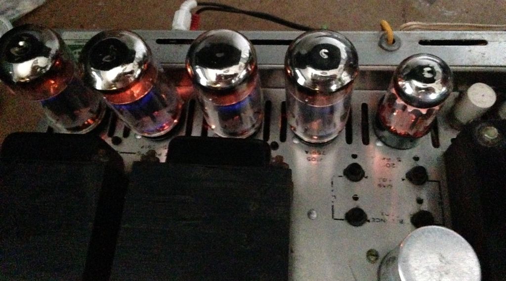
Hello guys have been working on the amp this weekend i cleaned all contacts ,tube sockets and checked everything without the tubes in using the method described everthing checked out good so i installed the new tubes and brought it up using the variac and the amp sounded great with my ipod plugged into the extra rca jacks no audio hum or capacitor hum nice and clean . i just wanted to make sure there were not any issues before i started recapping . the B+ is a little high though 465 volts at full wall power says 425 on the schematic .
then while it was playing i was preparing to turn it off the 5watt 270ohm wirewound resistor coming off of pin #1 on the rectifier tube popped and amp went silent .
i replaced it and it works great now but i am not going to turn it on again until after i recap it and check ALL resistors .
what are the best caps to use on this . i do have a large kit of orange drops but the change what type they are with values ??
Under 0.01uF are PNN Polypropylene Metal-Foil construction while 0.01uF and above are DME Metalized Polyester
would the be a good choice to use ?????
Wait, wait. You did not mention the most important attribute about the capacitors in a tube amp--the voltage rating.
Orange drop caps come in 100V, 200V and 400V ratings. None of those are suitable for a 465Volt anything.
Worry about your dielectric after finding suitable possibilities. Check your schematic carefully. And, yes, you can use a 400V cap where a 200 or 100V is specified but it is physically bulkier and may not fit.
(If I were you I would stop while I was ahead because re-capping old equipment can be very hard since the correct values are now extremely difficult to find in this age of +5V digital equipment.)
sorry about that the caps i have are rated for 630 volts . i restore antique boat anchors lol too [Hallicrafters} i get a lot of parts from here [http://www.justradios.com/ ] they have any capacitor rating you can get also a great range of carbon comp resistors too
Last edited:
Whew! (wipe off)
Glad you're on top of it. Carry on!
Tell us how it turns out. Wonderful old gear. More pics!
Glad you're on top of it. Carry on!
Tell us how it turns out. Wonderful old gear. More pics!
Hello guys have been busy the past couple weeks until this weekend so i have all the 716 orange drops and i am preparing to replace them but before i did i wanted to play it for a while and it started doing weird things i heard a click then lost audio then it clicked again and audio came back so i turned it off. now when i turn it on all tubes light up it just begins to have audio and makes a click sound and blows the fuse i replaced fuse with a 2 amp fuse and laid amp back down so i could see tubes powered it back up all tubes lit then i saw an arc in the rectifier tube and blew the fuse again . so i am not attempting to power it back up agian until i know what is causing this problem . i did test the rectifier tube in my tester it checked ok ???? the rectifier tube is a JJ GZ34
any ideas where to start looking .
Thanks
any ideas where to start looking .
Thanks
Last edited:
Yeah. 😉
Start by replacing all of the coupling capacitors and the electrolytic capacitors. Throw out the trashed JJ GZ34, and get a new one, once they have arced they cannot be trusted. (I would guess one of the electrolytics is now shorted, but it could be a variety of component failures in concert)
Never, ever replace a fuse with one larger than the one originally installed; power transformer HV secondaries do short under duress and if you are lucky the transformer is OK, if not you've created yourself a boat anchor.. You should never just replace the fuse and power it back up without figuring out why it blew in the first place.
Grab an extension cord and wire a lamp socket in series (not parallel) and install a 100 - 150W incandescent lamp and plug the amplifier into this for all future trouble shooting - it will protect expensive and irreplaceable components in the amplifier from damage. (Search for dim bulb tester etc here for more details)
i replaced the fuse with what came out a 2 amp slow blow i also forgot to mention i do have it plugged into a variac and was bringing it up slowly checking voltages then i saw the tube arc .
As you've discovered variacs without some means of current limiting (the lamp I mentioned) don't provide a whole lot of protection in the event of a fault and lull people into a sense of false security..
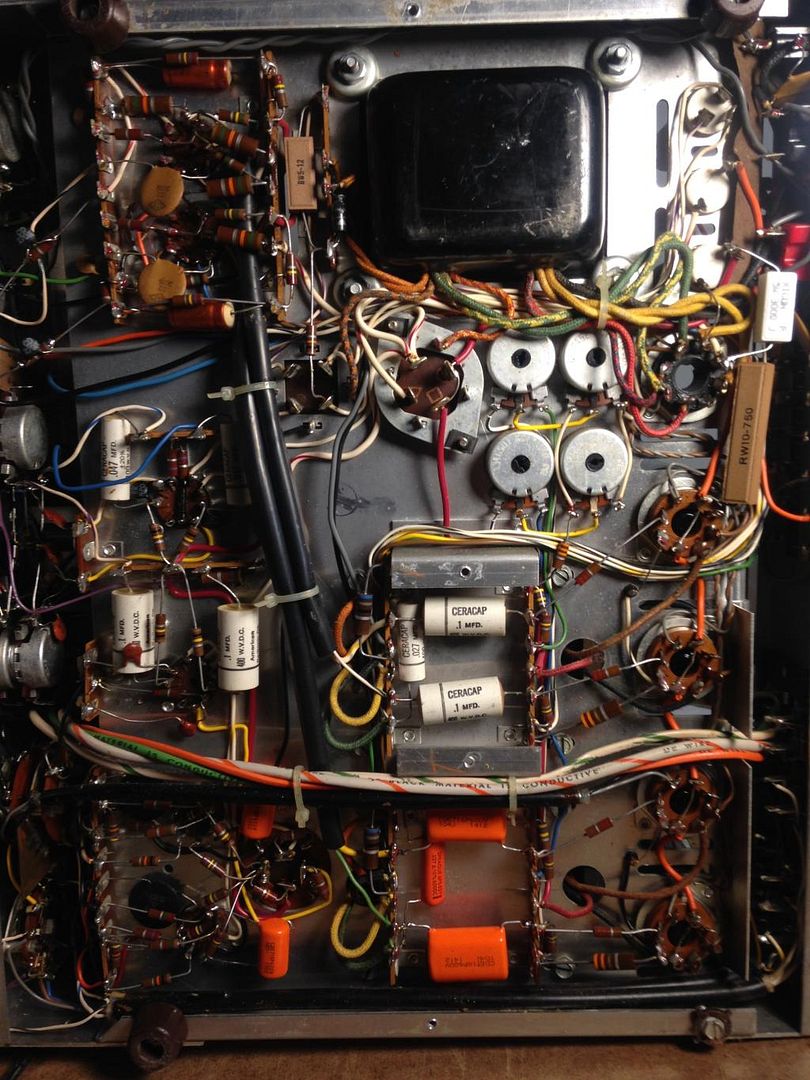
There a number of electrolytics in cans that likely need replacement at this point as well as a selenium rectifier that provides negative bias to the output stage and powers the tube filaments in the pre-amp portion of the amp. Note the caveats about the bias filter cap having a positive common - you won't find a modern replacement and will have to either empty out the existing can for new caps or find space for 4 el caps in the general area of the existing bias supply circuitry.
There a number of electrolytics in cans that likely need replacement at this point as well as a selenium rectifier that provides negative bias to the output stage and powers the tube filaments in the pre-amp portion of the amp. Note the caveats about the bias filter cap having a positive common - you won't find a modern replacement and will have to either empty out the existing can for new caps or find space for 4 el caps in the general area of the existing bias supply circuitry.
As you found, the hard way. JJ's Octal based production has serious reliability problems. 😡
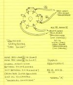
Put a Sovtek 5AR4 in the unit. Also, if you haven't already done so, add the SS diode tweak. Instead of the 1N4007s shown in the uploaded graphic, use UF4007s. UF4007s generate much less switching noise than 1N4007s. Even though the vacuum rectifier should suppress the SS generated noise, less noise, from the outset, has to be better.
Put a Sovtek 5AR4 in the unit. Also, if you haven't already done so, add the SS diode tweak. Instead of the 1N4007s shown in the uploaded graphic, use UF4007s. UF4007s generate much less switching noise than 1N4007s. Even though the vacuum rectifier should suppress the SS generated noise, less noise, from the outset, has to be better.
Attachments
I just made an executive decision LOL between not having a lot of spare time and having a Scott 299D i want working with piece of mind . I just got off the phone with Craig of NOS valves and sending unit to him . Will let you all know how it is when i get it back and will post some pictures . 😀
I just made an executive decision LOL between not having a lot of spare time and having a Scott 299D i want working with piece of mind . I just got off the phone with Craig of NOS valves and sending unit to him . Will let you all know how it is when i get it back and will post some pictures . 😀
This post will probably get moderated but I don't care. I have had several encounters with Craig and none of them were pleasant. Someone I know has one of his stereo units, not the VRD monoblocks. They were having a runaway bias issue and audible crackling coming from just the right channel. I offered to help but the owner of the amp was told by Craig to not let anyone touch it and to mail it to him for repair, we did try a different set of tubes and the problem was still there so it was surly the amp. After several weeks Craig asked for my buddy to send him the quad of RCA 6550's that were in the amp when the problem was happening😕 I do not know why and told my friend not to waste time and money sending him the tubes, he sent them anyway. After several more weeks and a rather large bill the amp was returned to my friend with a clean bill of health. Seriously after hooking it up the first thing the amp did was make horrible sounds out of the right channel and one tube was red plating. My buddy to say the least was furious. My friend was so upset I felt terrible for him. He agreed to let me take a crack at it, what do I know I mainly work on guitar amps lol. Anyway we drove over to my place and after putting the amp on my work bench and opening the amp up my buddy asked if I had any beer, I said sure and to go get us a couple from the fridge, after all this has been a very stressful day for my poor buddy. When he finally arrived back up the two fights of stairs with the frosty beverages in hand I was already done fixing the amp, I didn't even have to hook it up to a scope or anything. The problem was plain as day, the grid stop resistor that was mechanically fixed to pin 5 of that power tube was not soldered. I took some HI resolution photo's before I soldered it and sent them to Craig. He was apologetic but would not entertain the notion that he did anything wrong. He swore up and down that he did everything in his power to fix the amp even saying he listened to it for several days on his system without any issues. This is utter bullspit, if you even just touched that tube while the amp was on it would redplate and make crackling noises. I do not even think he looked at the amp, if he did he is a complete idiot, not to mention he charged quite a bit of money that he refused to refund.
Part two of the story. I had noticed that the octal sockets were breaking apart. Literally there were pieces inside the amp. If you use newer production tubes where the pins are larger they actually push the pin out the back side of the socket😱 I informed Craig and he was well aware of the horrible quality sockets used in those amps. I said well first you didn't fix your own amp correctly and now the sockets are crumbling, so I offered to replace the sockets for my friend so the amp doesn't have to be mailed across the country again. All I asked was that Craig mail some better sockets and or reimburse my buddy for having to buy new sockets. Craig's response was to the tune of "go F yourself, you will never get any of my hard earned money".
I strongly dislike this man, he will not discuss any technical issues, and I do not think he is an engineer, just a guy with a soldering gun that charges WAY too much money for his horrible services. I just want to warn you that you could end up paying tons of money for the rebuild when it is actually extremely easy to do yourself. I would at the very least look into sending it to somebody else for I do not think Craig is worthy of touching such nice gear.
Forget Craig, he is a loser.
Ok after reading this post do you have ant suggestions i am a little iffy now to say the least or with the help of the board get this issue fixed i have with the amp
I would be more than willing to help you fix up your stereo. With the help of some strong coffee I did my 299A in an afternoon. That included replacing the selenium rectifier with silicon for the preamp tubes, their associated capacitors, as Kevin pointed out you will not find a can replacement for this one but as myself and others have done is fit discrete caps along the tag board, there is plenty of room. I also replaced the coupling capacitors and other filter/decoupling capacitors.
I have some documents for you that I will scan and use some graphic editing software to show you visually what and where to replace. If you can follow directions and solder this forum will get you up and running🙂 And to think, when it's all done and you are enjoying some music on her you can look back and think to yourself "I did this". That my friend is the best feeling in the world.
I have some documents for you that I will scan and use some graphic editing software to show you visually what and where to replace. If you can follow directions and solder this forum will get you up and running🙂 And to think, when it's all done and you are enjoying some music on her you can look back and think to yourself "I did this". That my friend is the best feeling in the world.
First things first, since the rectifier arced and maybe damaged, floating the PT secondaries and using a dim bulb tester is a good way to start before ordering any parts. In any case if AC did arc from plate to cathode inside the 5AR4 all polarized caps could have been damaged so I would not try to hook up anything after the rectifier, especially without a dim bulb tester.
If you don't have a dim bulb tester this would be the time to make one, As stated a variac does not limit current. Not only does the dim bulb tester give you a visual indication of something wrong (it will start to glow really bright) but it doubles as a fuse🙂
I did see the photo's you posted before. Can you take more? Maybe one of the whole underside, that way there I can use image editing software to highlight the areas of discussion.
Yes i can take some more pics i will post them later this evening the serial number starts with 275 so it is a later model . i also have a new rectifier tube on the way . i will make the current limiter you are talking about tomorrow .😀
i sent you a PM with everything i have done so far
Thanks
i sent you a PM with everything i have done so far
Thanks
Ok i made the current limiter it works great i tried it on my SX42 boat anchor
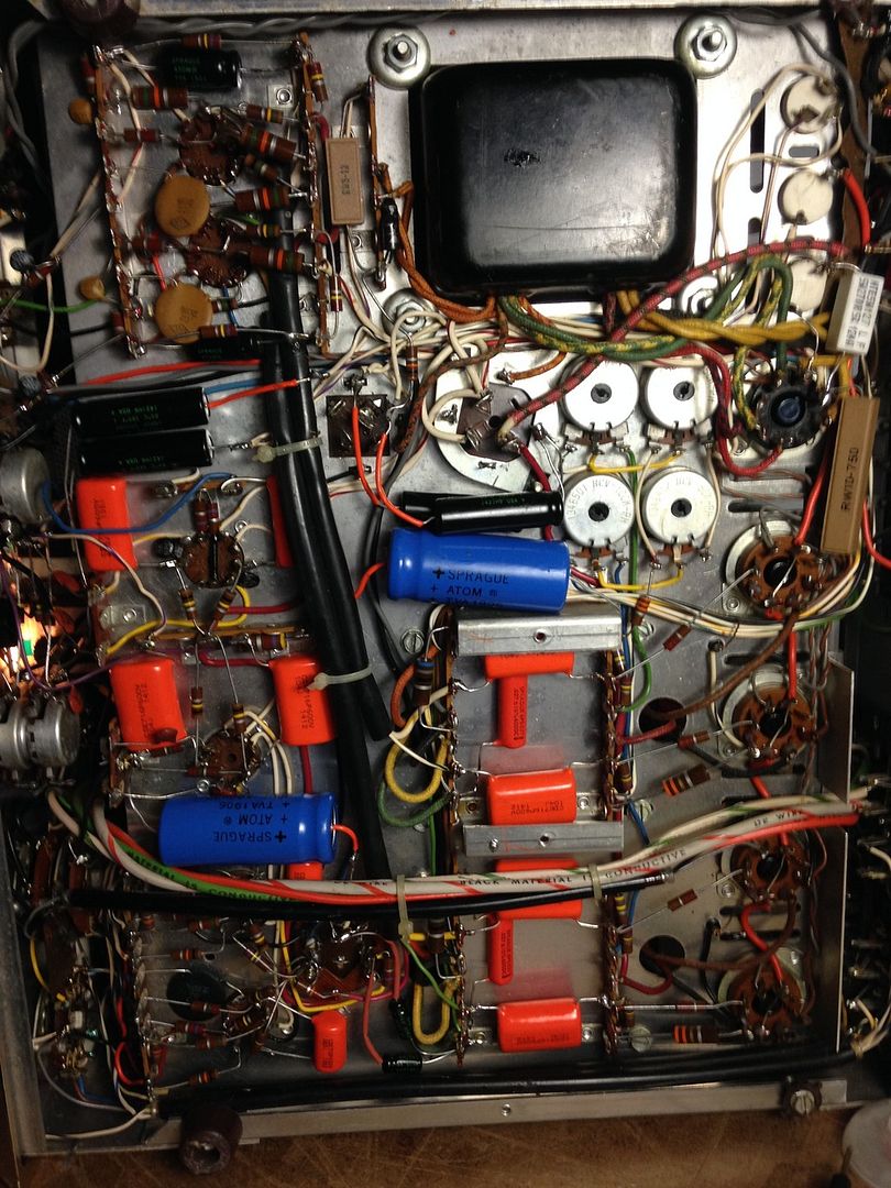
Here are a few pics of the unit from the bottom as you can see where i started installing the orange drops , also a picture of the current limiter
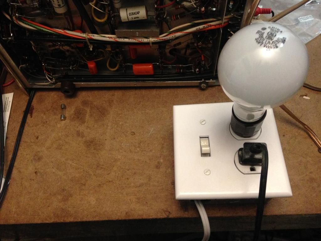
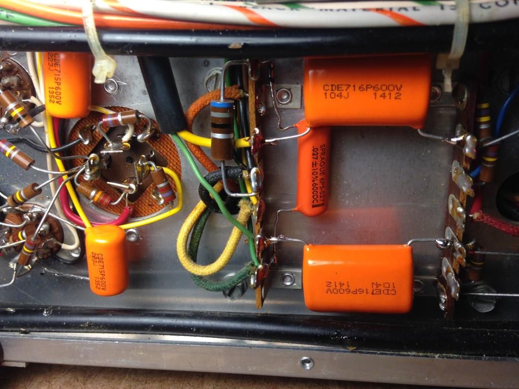
Here are a few pics of the unit from the bottom as you can see where i started installing the orange drops , also a picture of the current limiter
If, heaven forbid, it turns out that your power trafo is "shot", I have a good way to use the readily available Dynaclone ST70 replacement trafo in Scott 299C, 299D, LK72A and LK72B integrated amps. If Heyboer or 1 of the other working winders can provide an exact replacement for the OEM part, at competitive cost, then that's (obviously) the route to take.
Well i have some good news thanks to Jason [famousmockingbird] for giving me a hand on this one over the phone we bypassed the electrolytic can and tested the transformer under load and it is fine not blowing a 1 amp fuse 😀😀😀 . It appears something downstream has gone bad whew 🙂🙂 like one of the electrolytic caps
Hello guys after lots of painstaking work and lots of help from [famousmockingbird]
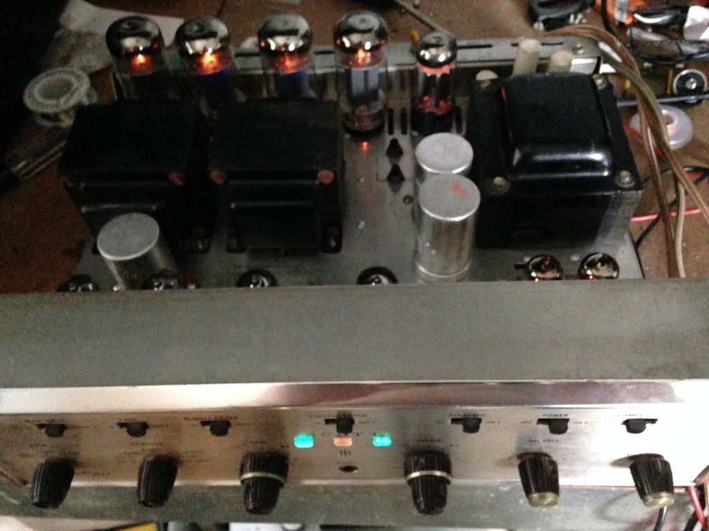
The Scott is back up and running like new with all new tubes coupling caps and electrolytic caps and plays and sounds fantastic . i replaced one can cap completely with a new one and the other 2 i disconnected them and fit axial caps underneath which was a task space is limited under there . ran into a few issues of course it kept blowing fuses [which was the initial problem before i started] but not until it got to about 105 volts turns out it was arcing at the rectifier tube connections and also the B+ lead going to resistor 206. after that problem was solved i set the tube balance and adjusted the bias and sent readings to [famousmockingbird] ,22 volts at test point 479 volts B+ at the rectifier tube 455 volts at the output tubes also -25 volts at pin6 of the output tubes . Man does this amp sound really good deep warm bass at all levels wow.
I also installed a new GOLDLION GZ34 rectifier tube made by Genalex .
Here are a few pics i still have tp do the cosmetic cleaning now but the hard part is over
Thanks Jason
- Status
- Not open for further replies.
- Home
- Amplifiers
- Tubes / Valves
- Scott 299D