Hi everybody, Im new to the forum, I recently purchased a scott 299c that was in need of repair.
The amp was all original, I put a new main filter capacitor on the 430v b+ to start. im new to tubes this being one of the first ones Im attempting to work on. Im hobbyist im 26 years old and by no means a professional. i have repaired quite a few solid state amps and other things in the past.
I do not own a variac im only using a dim bulb tester i do have a scope and multi meters.
So heres my first question, I powered up the amp with no output tubes (7591s) on a 60 watt bulb and the light didn't even glow. i was like cool looks like theirs no shorts and i can see the 5ar4, the phase inverters and 12ax7s glowing so things were looking good. so i decided to throw a set of jj7591s (jjs because i don't care if they get fried) in and see what happens, well with light bulb glowed bright. so I figured id jump up in wattage. Now using a 150 watt bulb the amp powers up the bulb goes {bright ish} real quick then dim... then after about 10 seconds or so it becomes bright again and the input line voltage drops to 80 volts. There is a slight audible hum and it dose pass a very small signal through my speakers (im not driving it hard), At this point idk if i need to go up in wattage on my bulb or if theirs a short happening. Also i do here a little buzzing sound intermittently coming from the amp.
I figured its because the bias is off and the tubes are pulling current and this is why but im just not sure and or experienced enough... problem is im afraid to give the amp full line voltage and due to this i cannot check the bias...
I am planing on changing all the coupling caps and the selenium rectifier once i get this thing up and somewhat running...
So i guess my question is should go up to a 200 watt bulb or dose it sound like i have other problems going on?
thanks in advanced!!!
its because the bias is off and the tubes are pulling current
Try turning the output tube DC bias pots to minimum, and center the output tube DC balance pots.
Then it should draw less current.
Last edited:
You have figured mostly correct. This is a common problem with all these old amplifiers. Don't go to a larger bulb. First, powering up the amp without the 7591 output tubes causes the B+ voltage to go higher then it normally would putting stress on the new filter capacitors. (worse for old ones) The bias voltage is taken from the DC filament voltage supply. This supply is powered by a full wave bridge rectifier that is selenium. It doesn't look like a normal American type (if original) because it's made in Germany. It's a brown brick. This item is most surely bad and putting out low voltage causing the bias voltage to be too low. With four 12 volt tubes in series, you need 48 volts at the end of the filter string. The schematic says 40 volts, but that is wrong IMO. It's possible that Scott wanted to run the low signal level tubes with a starved filament to help reduce hum. But that's really not necessary IMO. The four filter sections are probably bad also.I figured its because the bias is off and the tubes are pulling current and this is why but im just not sure and or experienced enough... problem is im afraid to give the amp full line voltage and due to this i cannot check the bias...
I am planing on changing all the coupling caps and the selenium rectifier once i get this thing up and somewhat running...
So i guess my question is should go up to a 200 watt bulb or dose it sound like i have other problems going on?
Replace the selenium bridge with a solid state bridge bolted directly to the chassis. I like to use a 4 amp size. Then determine if the filter capacitor is good or bad and replace if necessary. After doing this, determine if the output is 48 volts for the filament string. You can adjust the level a little by adjusting the value of the input resistor R214. You may also find that the four 12AX7s may have different voltages across their filaments (pins 4 & 5) due to different currents if you have modern replacement tubes installed. To correct this install 4 tubes of the same manufacture and production run. This will help assure even current among them. Perhaps not a problem it they're NOS tube.
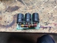
If finding a new mutli section capacitor is difficult, then single section units can be used mounted on a small board as seen in the picture below. There is also a link to the schematic in case you don't have it. After all the above is done, then check the coupling caps to the 7591s and replace if leaking or just old originals.
Schematic
Attachments

Last edited:
In this circuit there isn't separate bias adjustments. Only a balance adjustment. Bias voltage is fixed per the schematic.Try turning the output tube DC bias pots to minimum, and center the output tube DC balance pots.
Then it should draw less current.
Ok so i was kinda on the right track, and to hollowstate the 299c i have dose have bias pot adjustments, my main concern was that it was pulling so much current, but if you guys think its not out of the ordinary then i will move forward with changing out the rectifier. I have all the parts here i needed i just didn't want to move forward until i knew the current i was seeing was normal.
as for the over volt ing the filter cap i already changed out the main filters with 500v rated caps,
next new problem is i don't have a signal coming out the left channel. i checked the output trannys and they test good, plus i can here hum threw the speaker of the non working channel thankfully i was getting nervous for a second there. In relation to the tubes bias i noticed the left channel of the bias pots is turned more counter clockwise than the right channel.. could this be the reason im not getting a signal out of the left channel because the tubes are not biased on? or because the line voltage is only at 80 volts? or because something else is wrong...
Any pointers would be greatly appreciated.
so should i go ahead with changing out the bias rectifier?
so should i go ahead with changing out the bias rectifier?
Howdy,
I just did a fairly full restore & repair job on a Scott 296, which is about the same as your chassis, though the 296 uses 7581 tubes, stock. Haven't had time to read over your whole thread yet, but I caught this last question and wanted to let you know - "yes".
Replace the bias rectifier as a matter-of-course in these old amps. Many are selenium parts (not all) but it's still good to do, just so you have confidence. If you still have functional old-stock 7581 / 7591 power tubes, they're just too rare and expensive to needlessly screw up.
Does this design also use the bias supply as a DC filament supply for the front-end phono tubes, etc? That's a screwy arrangement, it totally starves the 12AX7 heaters - but apparently it works, so..
Diagnosing problems from afar with limited information is sometimes a guessing game. Unless your Scott has been modified to have 4 individual bias controls, it has only balance adjustments. Can you say for sure that is has 4 separate adjustments? (one for each 7591 tube) In any case, I think it is drawing too much current from the power supply if the 150 watt bulb lights brightly under quiescent operation. So replacing the selenium bridge for the bias/filament supply is crucial.
After replacing the rectifier, you must run the amplifier without the series bulb tester and take voltage measurements of the supply's output. Both at the output where the filament string connects (-48v) as well as the bias voltage at the 7591 control grids. (pin 6 approx -19v at all four). Only when the output stage is established and confirmed stable should you continue on. A nice big close up picture of the underside wiring would be helpful.
If you then have poor sound (volume) in one channel, you have another problem that must be found and corrected. And lack of signal can be caused by many things.
Ok yea misunderstanding, i have 2 bias pots and 2 dc balance pots, im aware i need to take the dim bulb out of line after i change the rectifier to get proper bias readings..
I got the other channel working now looks like one of my 12ax7s i had used was toast..
Thanks for all the help, im gonna try and tackle the rectifier tomorrow after work il keep updating as i move forward as im gonna need some input on things.
Thanks a bunch!!!
I got the other channel working now looks like one of my 12ax7s i had used was toast..
Thanks for all the help, im gonna try and tackle the rectifier tomorrow after work il keep updating as i move forward as im gonna need some input on things.
Thanks a bunch!!!
Something to be aware of is that the bias and filament supply filter cap (quad) is positive common so just any old part will not work here. The best solution is to remove the old can carefully, pull out its innards and replace with 4 modern caps wired for positive ground.
The selenium rectifier mentioned should be replaced, and adhering to the original schematic voltages allowing for the slightly higher prevailing line voltage is a good idea. The lowered filament voltage helps a little with things like 1/f noise in the phono stage and was deliberate. If you change the original Teles out you may want to adjust this upwards a bit because modern tubes may not always function well at 15% - 20% low filament voltage.
The selenium rectifier mentioned should be replaced, and adhering to the original schematic voltages allowing for the slightly higher prevailing line voltage is a good idea. The lowered filament voltage helps a little with things like 1/f noise in the phono stage and was deliberate. If you change the original Teles out you may want to adjust this upwards a bit because modern tubes may not always function well at 15% - 20% low filament voltage.
Hey thanks for the heads up i am going to get the voltage on the rectifier where it needs to be with some resistance. I am aware of the common positive cap on the bias supply and im going to do exactly what you mentioned as there is no room under the chassis.
Something to be aware of is that the bias and filament supply filter cap (quad) is positive common so just any old part will not work here. The best solution is to remove the old can carefully, pull out its innards and replace with 4 modern caps wired for positive ground.
The selenium rectifier mentioned should be replaced, and adhering to the original schematic voltages allowing for the slightly higher prevailing line voltage is a good idea. The lowered filament voltage helps a little with things like 1/f noise in the phono stage and was deliberate. If you change the original Teles out you may want to adjust this upwards a bit because modern tubes may not always function well at 15% - 20% low filament voltage.
Ok i put the new rectifier in, new problem i need help with because its on no schematic i have or could find.
so this amp has 2 bias pot adjustments it grabs the voltage right off the bridge before any of the 18ohm resistors and goes threw a 4700 ohm resistor that has now drifted low to about 3600 ohms... i did not lift it out of circuit yet to see if the low drift is due to that.
the can cap 75 75 75 75 is only filtering the filaments for the 12ax7s thats it...
anyways i assume this value would need to be raised to compassionate for the new bridge rectifier?? but how much ???
this is not shown on any schematic i can find but i do know that there was about 7 different ways they built the 299c... looks like mine is one of them.
the bias pots then go to the dc balance pots between the output tubes
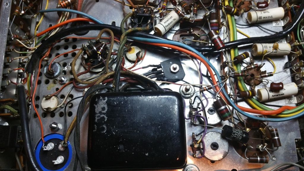
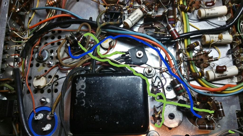
im including a picture so you guys can see what im talking about. one is a custom drawing lol showing where it goes... the green is the bias supply voltage and the blue is the supply voltage to the multi section filter caps that supply the filaments.
so this amp has 2 bias pot adjustments it grabs the voltage right off the bridge before any of the 18ohm resistors and goes threw a 4700 ohm resistor that has now drifted low to about 3600 ohms... i did not lift it out of circuit yet to see if the low drift is due to that.
the can cap 75 75 75 75 is only filtering the filaments for the 12ax7s thats it...
anyways i assume this value would need to be raised to compassionate for the new bridge rectifier?? but how much ???
this is not shown on any schematic i can find but i do know that there was about 7 different ways they built the 299c... looks like mine is one of them.
the bias pots then go to the dc balance pots between the output tubes
im including a picture so you guys can see what im talking about. one is a custom drawing lol showing where it goes... the green is the bias supply voltage and the blue is the supply voltage to the multi section filter caps that supply the filaments.
Last edited:
First off, the 75uF x4 cap tends to live a very long life in these amps. The cap in the amp I just serviced was in fine shape, and I didn't bother replacing it. It measured great on capacity, leakage and ESR tests - and leakage was tested at ~150% of rated voltage. Scoped waveforms looked just fine as well. There is also no reason to alter the value(s) of this cap, if you swapped out the bridge rectifier - that has no effect on it, why do you believe it might? Now if you're going to re-stuff it with new parts, upping the values is just fine, nothing will suffer for it.
You lost me here, can't tell what you're concerned with. Can you rephrase the question(s)? Also, I don't know that there are multiple variants of the 299C - there may be 299A/B and so on, but the 299C +should+ be covered by a standard schematic. Please show us which schematic you're working from - post it or link to it, whichever.
this is not shown on any schematic i can find but i do know that there was about 7 different ways they built the 299c... looks like mine is one of them
You lost me here, can't tell what you're concerned with. Can you rephrase the question(s)? Also, I don't know that there are multiple variants of the 299C - there may be 299A/B and so on, but the 299C +should+ be covered by a standard schematic. Please show us which schematic you're working from - post it or link to it, whichever.
Im sorry i guess that was hard to understand. What i was trying to say is if i should increase the resistance of the bias voltage supply resistor due to the new bridge rectifier.
Also the 299c had several different revisions to it, ive heard up to 7 different ways the 299c's were built. There are 2 schematics ive found available for the 299c both of which due not show the bias supply circuit my 299c has.. In fact none of the scott tube amps i look up do...
The can cap for the filaments of the 12ax7s is indeed testing ok on a atlas ecr but im changing them for safe keeping.
so should i up the resistance in the 4.7k?
Im sorry i guess that was hard to understand. What i was trying to say is if i should increase the resistance of the bias voltage supply resistor due to the new bridge rectifier.
In my experience, +no+. Just leave well enough alone for now. If you find out later that the bias voltage isn't where you need it to be, then revisit the issue at that time. And if it's like other Scotts of this ilk, you need all the bias / filament voltage you can muster. As I said, this supply starves the heaters of the 12AX7 tubes pretty seriously.
Also the 299c had several different revisions to it, ive heard up to 7 different ways the 299c's were built.
Then you have information beyond what I know.. I have no option but to defer to your findings, as I don't have your chassis or any of the various schematics in front of me.
The can cap for the filaments of the 12ax7s is indeed testing ok on a atlas ecr but im changing them for safe keeping.
Can't argue with that approach. Old electrolytic caps don't last forever, though some of them live far longer lives than you'd ever expect. Might be a matter of variable parts quality, service history (like, how much and how often was it used?) and plain old chance. My daily-driver shop stereo is an AM/FM stereo Fisher console chassis, from 1962 or so. It's been running for 8+ years, and the only power supply caps replaced are the two in the first stage HV doubler - as those parts are always suffering abuse.
so should i up the resistance in the 4.7k?
Lost me again, man. Which 4K7?
Ok i left it alone and fired it up on a 200 watt dim bulb. I had around 100v line voltage going in ad about 39v on the filaments and 38v on the bias pots. The amp is working great now!!
Im gonna leave the resistance alone like you suggested, the (4.7k)
Ok so next question, i understand how to adjust the dc balance. But where do i measure the bias? I have the 2 bias pots and dc balance pots on this amp. do i measure the voltage drop across the 3.3 ohm resistor on the red transformer leads? What should it be set to?
I'd need to see an owner's manual or schematic for your particular amp to give you any meaningful info on the bias set points - and that's for a couple of reasons. However, you can learn the basic values & limitations by consulting the datasheet for the tubes it uses (7591 / 7581?).
As for measuring the bias (current) in an unknown amp, without obvious bias test points, I use an.. unorthodox.. method for it. It goes like this:
You need an accurate DC ammeter set to read in the 50-100mA range. Red lead of the meter goes to the CT of the opt xfmr primary, the same point that's normally connected to the highest B+ voltage. Black lead goes to the Plate connection of the tube you wish to measure. So, if you have a simple push-pull amp, you'll make two measurements per channel - one for each tube.
The meter will read DC mA directly.. and it's just that easy. Obviously, the meter cannot be left connected, if the amp is being driven with signal. But this is a very quick and reasonably accurate way of reading bias current (that is, Plate current only) though any tube in the set.
It does not read cathode current, which is the sum of plate & screen. It only reads the plate current - but typically, that's fine - and mostly, it's all you really want to know.
Well the closest schematic to my 299c i could find was a scott 233 schematic, i see the test point but do i go to ground or measure across the 3.3 ohm? also i will be measuring in MV
http://www.hhscott.com/pdf/fs/233_299C.JPG
http://www.hhscott.com/pdf/fs/233_299C.JPG
Well the closest schematic to my 299c i could find was a scott 233 schematic, i see the test point but do i go to ground or measure across the 3.3 ohm? also i will be measuring in MV
You measure between the test point 'R' and ground - so yes, that's the same as measuring across the 3R3 1W. It indicates a value of +.22V, which is aka 0.220V or 220mV (DC).
- Status
- Not open for further replies.
- Home
- Amplifiers
- Tubes / Valves
- Scott 299c restoration help