Got a cheap scope that worked when it arrived, for about a week; it's a Tektronix T922R. All of a sudden, when I turned it on, the trace on both channels showed fine, but half of it outside the screen on the right side. The horizontal position button cannot bring it all the way to the center. As I turned it on and off a few more times, the trace moved more and more to the right, and now it's outside the screen.
Has any of you any ideas what might cause this?
Has any of you any ideas what might cause this?
ikoflexer said:Got a cheap scope that worked when it arrived, for about a week; it's a Tektronix T922R. All of a sudden, when I turned it on, the trace on both channels showed fine, but half of it outside the screen on the right side. The horizontal position button cannot bring it all the way to the center. As I turned it on and off a few more times, the trace moved more and more to the right, and now it's outside the screen.
Has any of you any ideas what might cause this?
http://www.logwell.com/tech/oscilloscopes/t921_922_sm.pdf
Ch. 7, "Sweep and Horiz amp"
Thank you, I've been browsing that chapter this morning. I was hoping someone would have had this problem, and have some specific advice, but I guess I'll have to start digging :/
First, verify that the horizontal mag control is fully counter clockwise in the X1 position. Next, you'll have to open the split case and check the low voltage power supply. This is the small board on the rear bottom side with the transformer. It has four outputs, +100v unregulated, +100v regulated, +8v and -8v. Measure these levels at the pin connector (P7) at the edge of the board. Pin 5 and the metal frame is the common ground.
Pin 1 is +100v reg.
Pin 2 is +100v unreg. (typically +120v)
Pin 3 is +8v
Pin 4 is -8v
While you are there, carefully inspect the solder connections at the P7 connector. Poor solder connections here are a very common problem in these scopes. This also applies to the other pin connectors used elsewhere. Both male and female counterparts.
If the output is low on one or more, you will need to find out why. Keep in mind that these supplies are current limited and will drop when loaded down heavily. So it could be the regulator itself or something downstream in the circuit.
If the supplies are up, you'll have to troubleshoot the horizontal section. (Remember those pin connectors.)
You must know the unit!
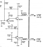
Did some poking and pulled the horizontal amp & sweep board out. Powered it with a lab supply, +8V, -8V, +100V. The voltage on the pins P2334 P2344 (sweep to crt) was skewed to positive +90V, and didn't change while turning the horizontal position pot. More poking and the problem ended up being Q2334 and Q2344, both 2N5551. Replaced them with a couple of mpsa42 that I had on hand and now the voltage on those two pins can be nicely balanced to approximately 50V each. Can't test it in the scope because I left it at work but I'm pretty sure it should work.
Thanks again for your pointers guys!
Attachments
hello.
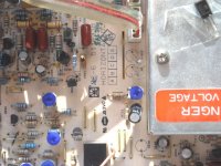
had the same problem with my leader scope,the horizontal trace moved to the left side and could not be moved to the right...........found out that a transistor (2sa1371) and a res (8,2k blue) in one half of the output stage of the horizontal board were damaged.......
built in new parts and it works again.
greets
Attachments
Last edited:
- Status
- Not open for further replies.