
Last edited:
What do you do with this ?
7.83Hz isn't really audio so you cant hear it or transmit it with a small board.
While 7.83 is supposedly the Earth's frequency .The only way I know it can be generated for use by a human is in the form of binaural waves with headphones.
I'd like to know it's application as shown.
Thanks.
Edit: OK , on looking at it again , are you suggesting that the 7.83 Hz is picked up and converted to a dc voltage which is eventually 'indicated' by the LED ?
Last edited:
It is similar to the one as following,
https://www.acoustic-revive.com/english/roomtuning/rr-77.html
Maybe you can reach more info there... cheers!
https://www.acoustic-revive.com/english/roomtuning/rr-77.html
Maybe you can reach more info there... cheers!
While the Schumann Resonance is nothing more than thunderstorms resonating around the Earth, but if a person was interested in experimenting with them what I would do is:
Modify the output of this circuit to drive a power amplifier. The amplifier would be a budget semi-pro Class "D" amp with several hundred watt output. It would need to have good low frequency response (almost down to DC). The load would be a 1000 foot roll of 18AWG magnet wire making several loops around the perimeter of room.
Modify the output of this circuit to drive a power amplifier. The amplifier would be a budget semi-pro Class "D" amp with several hundred watt output. It would need to have good low frequency response (almost down to DC). The load would be a 1000 foot roll of 18AWG magnet wire making several loops around the perimeter of room.
Last edited:
There is more here.
SCHUMANN RESONATORS
and
http://www.lessemf.com/schumann.html
More to do with generating biological 'harmony'. Doesn't affect the acoustics of the room but could affect 'hearing abilities' in a positive way. Wonder if it really works. All these are small boxes.
Speedskater's suggestion of having loops around the room seems to make more sense ?
I'm skeptic ! 🙂
One can always try a binaural signal with 7.83 Hz. Make a file using the old Cool Edit software. ( Cool Edit 96).
Last edited:
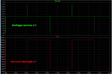
I put the schematic of post#1 into LTSPICE and ran some simulations. I found that the square wave output of the 555 IC, produced unpleasant looking waveforms at the "output inductor" L1.
Since the L/R timeconstant of the network on pin3 is only 5 nanoseconds (!) the exponential rise and fall of the inductor current is very quick, and the current is an excellent approximation of a square wave {red waveform}. Because the inductor voltage is proportional to the derivative of the inductor current (V = L*dI/dt), the voltage waveform is a Dirac delta function. An impulse. {green waveform}
Square waves and impulse trains are not the types of waveshapes found in resonances in the physical world. Plucked strings, struck bells, splashed pools all resonate with (slightly damped) sine waves. Thus I would expect the Schumann Resonance to be a sinusoidal phenomenon, personally. So I would expect that the optimum way to synchronize with it would involve sinewave, not square wave, currents in an inductor.
Thus I would expect better Schumann Resonance performance (whatever that is!), when people built a different circuit using opamps. This alternate circuit would generate a 7.83 Hertz sinewave, and apply this voltage sinewave to a "voltage controlled current source", thereby creating a sinusoidal current in the inductor.
_
Attachments
While the Schumann Resonance is nothing more than thunderstorms resonating around the Earth, but if a person was interested in experimenting with them what I would do is:
Modify the output of this circuit to drive a power amplifier. The amplifier would be a budget semi-pro Class "D" amp with several hundred watt output. It would need to have good low frequency response (almost down to DC). The load would be a 1000 foot roll of 18AWG magnet wire making several loops around the perimeter of room.
Here's a 76Hz transmitter...
https://www.hep.wisc.edu/~prepost/ELF.pdf
The amplitude of the Schumann resonances are 300uv/m and ~1 pico-Tesla respectively.
It is likely that "You have PM" in a Group Buy thread, means that someone has sent a Private Message to the thread starter (matcc), expressing willingness to purchase when the Group Buy happens.
Well I don't have any intention of buying. Just curious about what this was supposed to do. I most likely can build one if I want to which I don't ! But interesting to see what people are doing with it .
Follow-up to post #7:
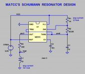
Figure 1 below shows a schematic that drives the coil with a sinusoidal current at 7.38 Hertz. It uses a 7805 voltage regulator IC (not shown) to provide a stable +5V supply from a 9V transistor radio battery, as was done in post #1.
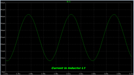
MCP607 5v-only, Rail-To-Rail-IO, quad opamp chips are used. Four opamps in a 14 pin package. Sections U1 and U2 generate a 7.38 Hz triangle wave, which feeds U3, a 3rd order Lowpass filter with proprietary pole/zero locations. U5 and U4 implement a voltage-to-current converter at the emitter of Q1. Since the collector current is ~ equal to the emitter current, a sinusoidal current flows in the broadcasting inductor L1 as well. This is plotted in Figure 2. Resistor R11 controls the amount of current that flows in the inductor.
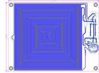
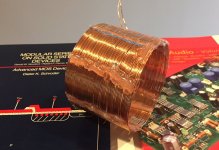
I've opted to use an air core inductor to get much higher inductance (235 uH) than the planar PCB inductor in post #1 (1 uH). I wound 60 turns of enamelled wire on the glass coil-former shown in Figure 3. Then I applied hot-glue to make the coil rigid and to fix each turn in place, before removing it from the coil former. Measured inductance is 235uH and measured DC resistance is 0.51 ohms. The coil itself is shown in Figure 4.
Am I going to coordinate a Group Buy for this? No. Indeed I will not. If someone else wants to do so, it's fine with me.
Edit- oops, I took the screen capture image when U1 was simulated with an LT1637. Sorry about that! It's really an MCP607 like all the others!
_
Figure 1 below shows a schematic that drives the coil with a sinusoidal current at 7.38 Hertz. It uses a 7805 voltage regulator IC (not shown) to provide a stable +5V supply from a 9V transistor radio battery, as was done in post #1.
MCP607 5v-only, Rail-To-Rail-IO, quad opamp chips are used. Four opamps in a 14 pin package. Sections U1 and U2 generate a 7.38 Hz triangle wave, which feeds U3, a 3rd order Lowpass filter with proprietary pole/zero locations. U5 and U4 implement a voltage-to-current converter at the emitter of Q1. Since the collector current is ~ equal to the emitter current, a sinusoidal current flows in the broadcasting inductor L1 as well. This is plotted in Figure 2. Resistor R11 controls the amount of current that flows in the inductor.
I've opted to use an air core inductor to get much higher inductance (235 uH) than the planar PCB inductor in post #1 (1 uH). I wound 60 turns of enamelled wire on the glass coil-former shown in Figure 3. Then I applied hot-glue to make the coil rigid and to fix each turn in place, before removing it from the coil former. Measured inductance is 235uH and measured DC resistance is 0.51 ohms. The coil itself is shown in Figure 4.
Am I going to coordinate a Group Buy for this? No. Indeed I will not. If someone else wants to do so, it's fine with me.
Edit- oops, I took the screen capture image when U1 was simulated with an LT1637. Sorry about that! It's really an MCP607 like all the others!
_
Attachments

Last edited:
So what do we do with this 'spirited coil' ?
If it was a huge coil around the room and one sat inside the room I'd get an idea of what's being done. But these small coils....what and how do they do whatever it is ?
If it was a huge coil around the room and one sat inside the room I'd get an idea of what's being done. But these small coils....what and how do they do whatever it is ?
So what do we do with this 'spirited coil' ?
If it was a huge coil around the room and one sat inside the room I'd get an idea of what's being done. But these small coils....what and how do they do whatever it is ?
Any coil will generate a solenoid field, easy to find references. A bundle of rebar up the coil helps a lot.
I wanted to know what the 7.38 Hz field does to us or something else !
There are probably hundreds of threads on the net discussing the effects of the Schumann frequency on humans. Audio related effects as well. Why do you feel the urgent need to pollute a group buy thread with your ignorance?
There are probably hundreds of threads on the net discussing the effects of the Schumann frequency on humans. Audio related effects as well. Why do you feel the urgent need to pollute a group buy thread with your ignorance?
Why do you get so upset with a simple question like that ? 🙂
Never mind . You don't need to reply to that....... Jeez !
- Status
- Not open for further replies.
- Home
- Group Buys
- Schumann Resonances based on 555 PCB