You were looking in the wrong place for the phase splitter.Marek, could you clarify your comment. I don't get your point. That circuit simply can not work.
V2 isn't there to "balance it's input signals" - it takes an input signal on the bottom v2b valve and forces an antiphase output on the top v2b valve by virtue of their shared cathode resistor. It's the phase splitter you were looking for! The circuit does not care a jot what is on the grid of the top v2b - that is an unwanted balancing item which gets earthed out at the v1b grid. The primary function of V2 is as a phase splitter not a driver stage of antiphase inputs as you originally thought.Of course the V2 as it is a differential stage with relatively large tail resistor will balance the huge difference of its input signals
If that were true, you could take it out.At the schematic discussed V1b has no function.
It's function is to provide the bias point for the top v2b valve.
We all know these see-saws (i.e. V2b x2)don't balance well because one side is an inverter and one side a follower and a cathode follower doesn't have a gain of exactly 1, so mismatching the v2b loads (as Koonw points out) is needed.
kind regards
Marek
I correct my earlier statement. This circuit as a whole is not fully inoperative, but just very poor design.
V2 is a differential amplifier. Both grids receive AC-signal that is at opposite phase, but at the grid of V2b it is much smaller.
As the stage has a common tail resistor (though too small to say it is optimum) the anti phase signal exist at the plates of V2 but not very well balanced.
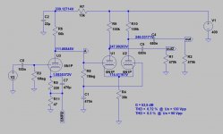
V1b can be taken away. The bias for direct coupled LTP usually is taken from the anode of a single voltage amplifying stage.
Attached a schematic of a typical voltage amplifier + LTP. No extra tube needed just for bias.
V2 isn't there to "balance it's input signals" - it takes an input signal on the bottom v2b valve and...
V2 is a differential amplifier. Both grids receive AC-signal that is at opposite phase, but at the grid of V2b it is much smaller.
As the stage has a common tail resistor (though too small to say it is optimum) the anti phase signal exist at the plates of V2 but not very well balanced.
V1b has no function.
If that were true, you could take it out.
It's function is to provide the bias point for the top v2b valve.
V1b can be taken away. The bias for direct coupled LTP usually is taken from the anode of a single voltage amplifying stage.
Attached a schematic of a typical voltage amplifier + LTP. No extra tube needed just for bias.