Hi everyone!
I have a PPI A600 (not .2) with a problem in drivers-predrivers section.
I'm becoming mad because something is missing, or i'm to tired to find the problem😛
Anyone has a schematic or semplified schematic like Perry's?
The amplifier works without predrivers, but when a put them in, they heat and the amp draw excessive current.
Another channel works ok with new predrivers (2SC2389 + complementary) instead of original 2N5551 and 2N5401.
I don't have thats 2N's at home.
The right channel has this voltage on output stage:
- base: +-0.8V
- collector: 40 or -40 (depend of NPN or PNP)
- emitter: 0V
But broken channel, with predrivers, is:
- base: +-39V😡
- collector: +-40V
- emitter: +-39V😡
that voltage are egual with or without output stage.
predrivers & PNPs (new BD912) heat very very much😡
drivers are cool and ok (i replace them but nothing solved)
I have a Perry's schematic for a 2150AM but it's too different from A600🙁
thank you!
ciao!
Pergo is this the amp your talking about < see link below >
Precision Power A600 - Amp Guts
If so you most likely has a bad SIP driver card IMO. SIP cards are not available but many times they can be repaired by carefully touching up the solder joints on them. Careful too much heat will destroy the solder pads on these ceramic cards, and most liquid solder flux's are not well accepted either. < I.E. flux does not help in most cases and may lead to pad failure...Been there, done that, Not good.
I do not have a A600 pdf. Perhaps someone else might though....🙂
the amplifier is similar to that:
Precision Power A600 inside - Amp Guts
but i've:
- diode fast bridge is AKA & KAK, not 4 single diode.
- filter toroid (after AKA+KAK bridge) is different, much "older" and handmade.
- drivers are different. Mine has 2SCxxxx + 2SAxxxx in plastic to220.
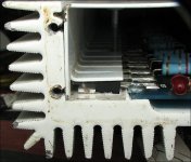
After the first repair (replace output stage with new BD911 & BD912) the amplifiers shows a little DC offset in the bottom channel (see image).
The DC offset was 100mV.
Then, i turn the potentiometer to the bottom right angle (see image) for set DC offset and it goes to 8mV.
I test that channel with 3ohm pure resistive dummy load, but over 100Wrms the BD912s fails (only 1).
I replace it, and re-test. Again, over about 100Wrms, same bank of BD912 fail (but another position).
Before the failure there's no distortion or other.
It takes about 3 minutes @100Wrms continuously before failure.
Then, i re-replace the BD912s...but the amplifier draws excessive current and goes on overcurrent protection.
I kept it in protection for 1 minutes and i heard a "chop!" (little high frequecy explosion) but i can find the component that fails. No smoke!
I touch everything and i've noticed that SIP card heat too much.😡
I desolder BF722 & BF723 but still same problem.
I desolder 1B & 3B (BC546 & BC556 in SOT23) that had 0 resistance between two leg (copying the other SIP card).
Now, the pre-drivers (or VAS?) heat. They're 2N5551+2N5401. I replace with different new components (BC546 + BC557, or 2SC2389+complementary, or MPSA06+MPSA56) but still same problem.
If i remove pre-drivers (or VAS?), the amplifer work at idle. No protection, but that channel cannot sound (obviously).
The other channel is ok.
I test every resistor, changed (with new parts) every transistor for broken channel, but the problem isn't here.
Remains only the SIP card, my fear!!😡
There are BF722 & BF723 and some pairs of 3B & 1B in SOT23. When i desoldered them, no fluid🙂
and image:
http://img534.imageshack.us/img534/6791/immagineiw.jpg
ps: Perry, email sent
Precision Power A600 inside - Amp Guts
but i've:
- diode fast bridge is AKA & KAK, not 4 single diode.
- filter toroid (after AKA+KAK bridge) is different, much "older" and handmade.
- drivers are different. Mine has 2SCxxxx + 2SAxxxx in plastic to220.
After the first repair (replace output stage with new BD911 & BD912) the amplifiers shows a little DC offset in the bottom channel (see image).
The DC offset was 100mV.
Then, i turn the potentiometer to the bottom right angle (see image) for set DC offset and it goes to 8mV.
I test that channel with 3ohm pure resistive dummy load, but over 100Wrms the BD912s fails (only 1).
I replace it, and re-test. Again, over about 100Wrms, same bank of BD912 fail (but another position).
Before the failure there's no distortion or other.
It takes about 3 minutes @100Wrms continuously before failure.
Then, i re-replace the BD912s...but the amplifier draws excessive current and goes on overcurrent protection.
I kept it in protection for 1 minutes and i heard a "chop!" (little high frequecy explosion) but i can find the component that fails. No smoke!
I touch everything and i've noticed that SIP card heat too much.😡
I desolder BF722 & BF723 but still same problem.
I desolder 1B & 3B (BC546 & BC556 in SOT23) that had 0 resistance between two leg (copying the other SIP card).
Now, the pre-drivers (or VAS?) heat. They're 2N5551+2N5401. I replace with different new components (BC546 + BC557, or 2SC2389+complementary, or MPSA06+MPSA56) but still same problem.
If i remove pre-drivers (or VAS?), the amplifer work at idle. No protection, but that channel cannot sound (obviously).
The other channel is ok.
I test every resistor, changed (with new parts) every transistor for broken channel, but the problem isn't here.
Remains only the SIP card, my fear!!😡
There are BF722 & BF723 and some pairs of 3B & 1B in SOT23. When i desoldered them, no fluid🙂
and image:
http://img534.imageshack.us/img534/6791/immagineiw.jpg
ps: Perry, email sent
Last edited:
yes, for burn-in test for rock-solid stability operation.
I use 50Hz from Mp3-home-player
other channel works fine with that signal.
every amplifier i've repaired, then i test it with dummy load and max power.
is it wrong?
thank you
I use 50Hz from Mp3-home-player
other channel works fine with that signal.
every amplifier i've repaired, then i test it with dummy load and max power.
is it wrong?
thank you
A constant sine wave into a dummy load is much tougher than the same output level into a speaker with music.
Are the mica insulators perfectly intact? If they're split or separating, they may not be conducting heat as well as they should. Some of these amps have a lot of powdercoating under the transistors. If you think the failures are related to the heating of the outputs, you may want to sand the powdercoating off to promote better heat transfer.
Have you removed 100% of the old compound and replaced it with new heatsink compound?
If the amp survives playing music up to and into clipping, it's probably OK. Of course, you have to get it repaired before any of this information is of any use.
i check mica insulator, it's ok. i don't replace thermal compound.
The amplifier dissipates well.
Before the failure, output stage and chassis were at about same temperature.
Not untouchable, but little hot (maybe 50°C). No overtemp protection goes on.
I know that sine is more than music, but i avoid clipping when i use dummy load.
I always start with low power continuously (like 50W), then i increase.
Long time ago i used speakers, but the persistent loud music make me crazy😀😀
I test it @lab, where 500Wrms destroy the walls😛😛
I hope to finish my car-audio system in a month, to test it in the car😉
Most amps can survive music up to and into clipping with a dummy load but a pure sine wave is more than some amps can take.
If the amp wasn't hot, there may be other problems. With these amps, you have to make sure that the transistors are laying flat against the sink before reinstalling the cover.
If the amp wasn't hot, there may be other problems. With these amps, you have to make sure that the transistors are laying flat against the sink before reinstalling the cover.
In the attached photo, you can see that the transistor isn't laying against the sink. The corner of the bottom/base of the transistor dug into the mica and wouldn't lay down. The 'finger' applying pressure to it was perfectly inline (not sprung) when the cover was removed to lay it down properly. This sort of problem can cause the transistors to fail prematurely.
Attachments
damn clamp method😛
maybe i'll desolder each transistor and re-mount it with care, to avoid premature failure like your image😉
however, maybe i find the problem in the SIP driver card, as i write to Perry via email.
There were 2 transistors (3B and 1B = BC856B and BC846B) shorted.
Without them, i've wrong voltages on base and emitter in output stage.
maybe...........😛
i'll buy it tomorrow😉
Last edited:
You don't have to desolder any transistors to make them lie flat.
1-remove board from sink
2-clean off all thermal paste
3-temporarily install board into sink
4-put a small amount of flux on each leg solder point
5-while applying firm pressure to the transistor to make it sit flat, solder each leg (b,c,e,b,c,e) or (g,d,s,g,d,s) just a touch to readjust and take stress off the legs to allow the transistor to lie flat
6-repeat with all transistors
You can do this without removing the thermal paste but sometimes there are dry spots that aren't as soft and wont' allow the proper angle
thank you for the suggest.🙂🙂
now my objective is make it works at idle, with no protection, no excessive draws, etc.
Then i'll fix the transistor position to make a sure clamp😉
1.34A @idle @12V is correct? (bias pot set at 1pm)
now my objective is make it works at idle, with no protection, no excessive draws, etc.
Then i'll fix the transistor position to make a sure clamp😉
1.34A @idle @12V is correct? (bias pot set at 1pm)
1.34A @idle @12V is correct? (bias pot set at 1pm)
by chance did you install the jumper on the two pin header located in the middle of the output section near the edge of the board ?????
As I recall from my PPI friend that this is needed to bypass the thermal tracking so the bias can be set properly, and then the jumper is removed. I set the bias while viewing a sine wave on a scope at 1/4 watt and 1 watt levels. This should get it set correctly so their is no crossover distortion. I also have a set of handy Vise-grip clamps that hold the outputs down to the sink while I do all this bias adjusting.
And I always replace all of the silicon heat sink compound with fresh, and clean all the mica insulators and inspect for non-uniformity and degradation and such like metal fragments embedded into them which causes shorts to the case. PPI flooded these amps with compound when they built them. I think they may have known about their clamp issues and thought compound flooding would over come most line production issues.😱 I also suggest straightening of the clamp bars on the case bottom so they all sit uniformly and apply pressure equally before re-assembly.

The metal fragments usually come form the bottom cover screws and are always present in the old silicon compound, hence the cleaning that needs to be done.
Also be very careful tightening the bottom case or you will need to install Keen-serts, or Heli-coil thread repair kits. Something to do with steel screws into aluminum heat sink, go figure eh?🙂
I have never seen any documented bias idle current draw spec's for PPI amps. And everyone I ever saw had different setting so I shoot from the hip and use the above method to set them up. Its a pain but I never saw much in the way of rework by doing it this way, and the amps always sounded nice when it was done.....Oh and also revisit your DC offsets after the bias is set cause they will drift with bias alignment. It will be a bit of a back and forth till its all set correctly and sounding sweet. But you will hear the difference between not set and set. PPI's sounded very good for their time, if they were setup correctly with very little DC offset and proper output biasing.
Hope this helps.🙂
thank you for the reply🙂🙂
i don't see any jumper in my board😕😕😕
well, about the bias. Between minimum and maximum, the current goes from 1.3A to 1.5A. It's only a 100ohm pot, for fine adjustment.
However, there's no crossover distortion before the first failure.
Thursday i'll buy new BJTs for driver card.
For safety, i'll buy some 2N5551 and 2N5401 that i've finished😛
hi!,
i have some updates.😛
Last week arrived new parts, like 2N5551, 2N5401 for predriver and output protection, and some B3 and B1 in SOT23 package for driver board.
Today i mount them but the amplifier won't work.🙄
The output stage heat a lot.😡
Then, after thousand of "damn it!" (like Jack Bauer😀), i've desoldered every NEW output BJT for testing with Digital Multimeter.
Another thousand of "damn it!". One of 8 BJTs (a BD911) was fake...i mean, it was build with a failure. Base-Collector test said 600 for each good BD911, but that one was only 300😱😱😡😡😡 not shorted, but low resistance🙄
That BJTs came from the same stock...same week, same date, etc...🙁
Now, i replace with new BD911 (everyone good😉) and the amplifier works😀😀
A lot of wasted time for a factory-failed component🙁
It never happened to me. Every parts i bought (original, obviously) was good.
That story teaches me, that i always have to test every components i wanna mount!
Thank you guys, especially "the King" Perry, for every answer gave me by email🙂
Ciao!
there is another problem😡😡😱😱
I've repaired the amplifier. Yesterday i try it with a Music CD (rock) and it plays well at 50% power for an hour.
It goes very very hot, but it sounds good.
Then, i took a rest and after an hour, i try a IASCA cd test for subwoofer..always 4ohm stereo with dummy load.
After 2 minutes it failed.😡
I check output transistor and NPNs where shorted (only one bad).
I replace it with another BD912 (always by ST) but after a minutes, with low music (1/4 of power) it failed.
Same BD912.
I replace...then it re-failed..same BD912..
For 5 times up to now (i finished BD912😛).
In that 5 times i changed mica with siliconic sheet..but nothing.
Emitter resistor are ok (i measure them with a volt-amperometric method).
I think there's a mistake with the clamp method. I hate that!
I'm thinking about a new clamp method, like Orion: a 3-4mm thickness aluminium bar, to make a sure clamp for all transistors and mosfets.
Like Orion, i'll pull down it with 4 or 6 screw.
What do you think about that idea?
Or i've to replace always all the PNPs output transistor and not the only one shorted?🙄
The difference in mine BD912s is the production week: 830 vs 835🙄
p.s:
Vbe is set, for both channel, to 0.5V by bias pot.
DC Offset was adjusted to 0v by potentiometer (real value is about 2mV)🙄
DC offset potentiometer are in a very different position from original. Original position is about 1 o'clock (60%), but now, one is at 10% (9 o'clock), other at 70% (2 o'clock)
The DC offset trimming is made after 30 minutes of idle.
- Status
- Not open for further replies.
- Home
- General Interest
- Car Audio
- Schematic Precision Power A600